Configure policy-based routing
Configure PBR to enable direct internet access for specific web-based applications, optimize traffic flow, and achieve load balancing between WAN and VTI interfaces.
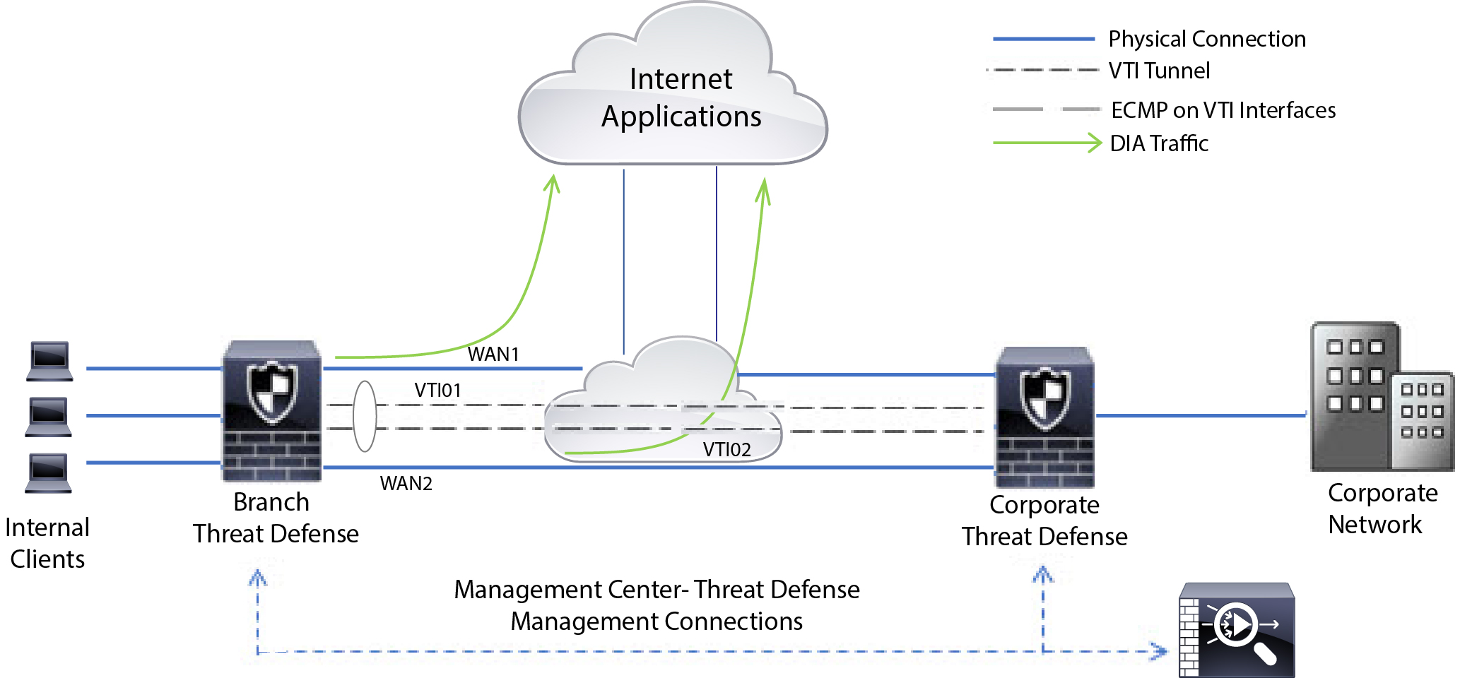
Consider a typical corporate network scenario where all the branch network traffic passes through a route-based VPN of the corporate network and diverges to the extranet, when required. Accessing web-based applications through the corporate network to support daily operations may increase network size and maintenance costs. This example illustrates how to configure PBR for direct internet access.
The following figure depicts the topology of a corporate network. The branch network is connected to the corporate network through a route-based VPN. Traditionally, the corporate Firewall Threat Defense is configured to handle both the internal and external traffic of the branch office. With the PBR policy, the branch Firewall Threat Defense is configured with a policy that routes specific traffic to the WAN network instead of the virtual tunnels. The rest of the traffic flows through the route-based VPN, as usual.
This example also illustrates how to configure the WAN and VTI interfaces with ECMP zones to achieve load balancing.
Before you begin
This example assumes that you have already configured WAN and VTI interfaces for the branch Firewall Threat Defense in Cloud-Delivered Firewall Management Center.
Procedure
Step 1 | Configure policy-based routing for the branch Firewall Threat Defense, select the ingress interfaces:
| ||
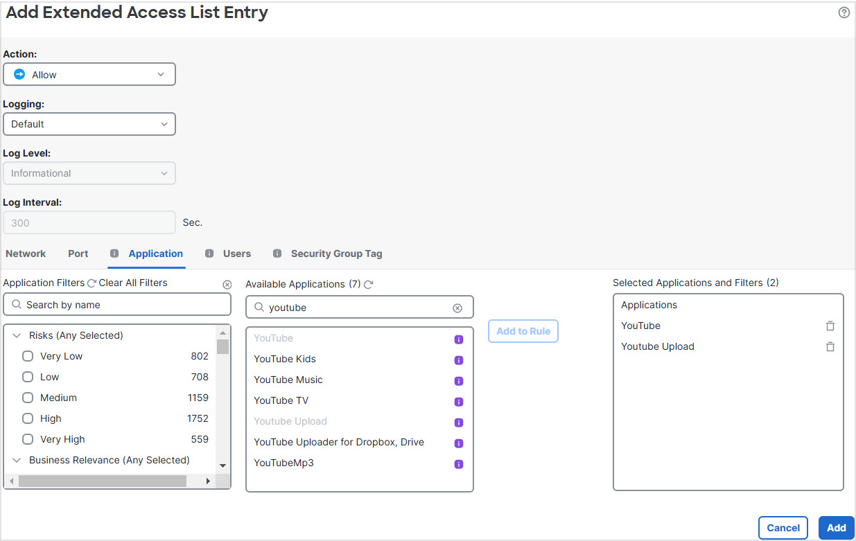
Step 2 | Specify the match criteria:
| ||
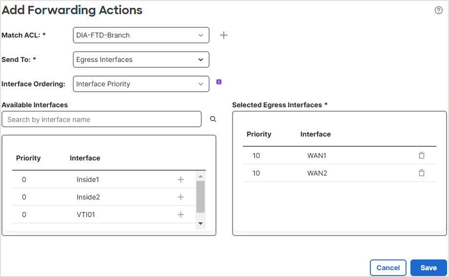
Step 3 | Specify the egress interfaces:
| ||
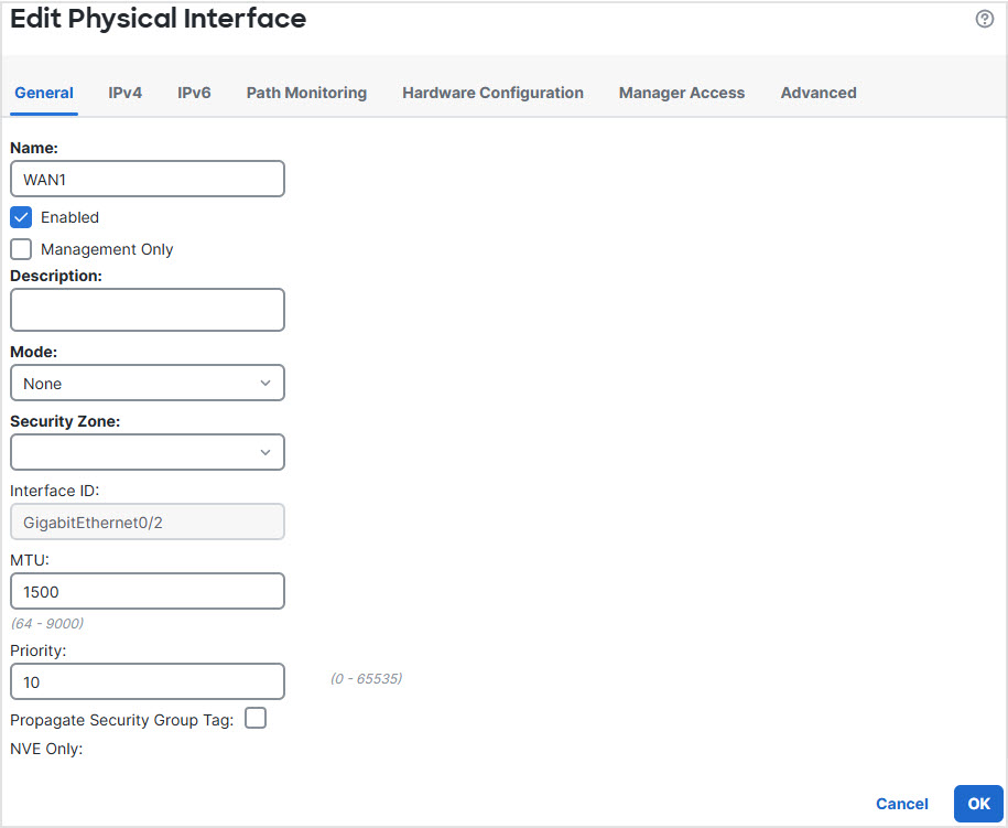
Step 4 | Configure interface priority: You can set the priority value for the interfaces either in the Edit Physical Interface page, or in the Policy Based Routing page (Configure Interface Priority). In this example, the Edit Physical Interface method is described.
| ||
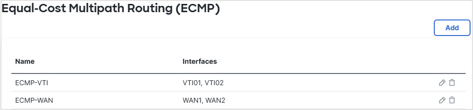
Step 5 | Create ECMP zones for load balancing:
| ||
Step 6 | Configure static routes for the zone interfaces for load balancing:
| ||
Step 7 | Configure trusted DNS on the WAN objects of the branch Firewall Threat Defense to ensure secure flow of traffic to the internet:
| ||
Step 8 | Click Save, and then click Deploy. |

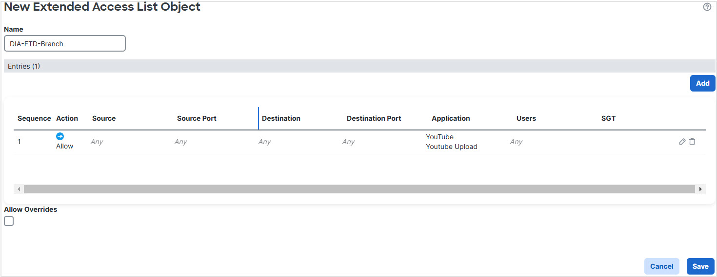
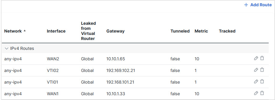
Any YouTube related access requests from the branch inside network INSIDE1 or INSIDE2 are routed to WAN1 or WAN2 as they would match the DIA-FTD-Branch ACL. Any other request, say google.com, are routed through VTI01 or VTI02 as configured in the Site to Site VPN Settings.
With the ECMP configured, the network traffic is seamlessly balanced.