Configure Dynamic Manual PAT

Use dynamic manual PAT rules when auto PAT does not meet your needs. For example, if you want to do different translations based on the destination. Dynamic PAT translates addresses to unique IP address/port combinations, rather than to multiple IP addresses only. You can translate to a single address (either the destination interface's address or another address), or use a PAT pool of addresses to provide a larger number of possible translations.

Before you begin

Select Objects > Object Management and create the network objects or groups needed in the rule. Groups cannot contain both IPv4 and IPv6 addresses; they must contain one type only. Alternatively, you can create the objects while defining the NAT rule. The objects must also meet the following requirements:

  • Original Source—This can be a network object or group, and it can contain a host, range, or subnet. If you want to translate all original source traffic, you can skip this step and specify Any in the rule.

  • Translated Source—You have the following options to specify the PAT address:

    • Destination Interface—To use the destination interface address, you do not need a network object.

    • Single PAT address—Create a network object containing a single host.

    • PAT pool—Create a network object that includes a range, or create a network object group that contains hosts, ranges, or both. You cannot include subnets.

You can also create network objects or groups for the Original Destination and Translated Destination if you are configuring a static translation for those addresses in the rule.

For dynamic NAT, you can also perform port translation on the destination. In the Object Manager, ensure that there are port objects you can use for the Original Destination Port and Translated Destination Port. If you specify the source port, it will be ignored.

Procedure


Step 1

Select Devices > NAT and create or edit the threat defense NAT policy.

Step 2

Do one of the following:

  • Click the Add Rule button to create a new rule.
  • Click Edit (edit icon) to edit an existing rule.

The right click menu also has options to cut, copy, paste, insert, and delete rules.

Step 3

Configure the basic rule options:

  • NAT Rule—Select Manual NAT Rule.
  • Type—Select Dynamic. This setting only applies to the source address. If you define a translation for the destination address, the translation is always static.
  • EnableWhether you want the rule to be active. You can later activate or deactivate the rule using the right-click menu on the rules page.
  • InsertWhere you want to add the rule. You can insert it in a category (before or after auto NAT rules), or above or below the rule number you specify.

Step 4

On Interface Objects, configure the following options:

  • Source Interface Objects, Destination Interface Objects(Required for bridge group member interfaces.) The interface objects (security zones or interface groups) that identify the interfaces where this NAT rule applies. Source is the object containing the real interface, the one through which the traffic enters the device. Destination is the object containing the mapped interface, the one through which traffic exits the device. By default, the rule applies to all interfaces (Any) except for bridge group member interfaces.

Step 5

(On the Translation page.) Identify the original packet addresses, either IPv4 or IPv6; namely, the packet addresses as they appear in the original packet.

See the following figure for an example of the original packet vs. the translated packet.
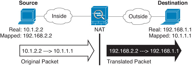
  • Original Source—The network object or group that contains the addresses you are translating.

  • Original Destination—(Optional.) The network object or group that contains the addresses of the destinations. If you leave this blank, the source address translation applies regardless of destination. If you do specify the destination address, you can configure a static translation for that address or just use identity NAT for it.

    You can select Source Interface IP to base the original destination on the source interface (which cannot be Any). If you select this option, you must also select a translated destination object. To implement a static interface NAT with port translation for the destination addresses, select this option and also select the appropriate port objects for the destination ports.

Step 6

Identify the translated packet addresses, either IPv4 or IPv6; namely, the packet addresses as they appear on the destination interface network. You can translate between IPv4 and IPv6 if desired.

  • Translated Source—One of the following:
    • (Interface PAT.) To use the address of the destination interface, select Destination Interface IP. You must also select a specific destination interface object. To use the IPv6 address of the interface, you must also select the IPv6 option on Advanced. Skip the step for configuring a PAT pool.

    • To use a single address other than the destination interface address, select the host network object you created for this purpose. Skip the step for configuring a PAT pool.

    • To use a PAT pool, leave Translated Source empty.

  • Translated Destination—(Optional.) The network object or group that contains the destination addresses used in the translated packet. If you selected an object for Original Destination, you can set up identity NAT (that is, no translation) by selecting the same object.

Step 7

(Optional.) Identify the destination service ports for service translation: Original Destination Port, Translated Destination Port.

Dynamic NAT does not support port translation, so leave the Original Source Port and Translated Source Port fields empty. However, because the destination translation is always static, you can perform port translation for the destination port.

NAT only supports TCP or UDP. When translating a port, be sure the protocols in the real and mapped service objects are identical (both TCP or both UDP). For identity NAT, you can use the same service object for both the real and mapped ports.

Step 8

If you are using a PAT pool, select the PAT Pool page and do the following:

  1. Select Enable PAT pool.

  2. Select the network object group that contains the addresses for the pool in the PAT > Address field.

    You can alternatively select Destination Interface IP, which is another way to implement interface PAT.

  3. (Optional) Select the following options as needed:

    • Use Round Robin AllocationTo assign addresses/ports in a round-robin fashion. By default without round robin, all ports for a PAT address will be allocated before the next PAT address is used. The round-robin method assigns one address/port from each PAT address in the pool before returning to use the first address again, and then the second address, and so on.

    • Extended PAT TableTo use extended PAT. Extended PAT uses 65535 ports per service, as opposed to per IP address, by including the destination address and port in the translation information. Normally, the destination port and address are not considered when creating PAT translations, so you are limited to 65535 ports per PAT address. For example, with extended PAT, you can create a translation of 10.1.1.1:1027 when going to 192.168.1.7:23 as well as a translation of 10.1.1.1:1027 when going to 192.168.1.7:80. You cannot use this option with interface PAT or interface PAT fallback.

    • Flat Port Range, Include Reserved PortsTo use the 1024 to 65535 port range as a single flat range when allocating TCP/UDP ports. (Pre-6.7) When choosing the mapped port number for a translation, PAT uses the real source port number if it is available. However, without this option, if the real port is not available, by default the mapped ports are chosen from the same range of ports as the real port number: 1 to 511, 512 to 1023, and 1024 to 65535. To avoid running out of ports at the low ranges, configure this setting. To use the entire range of 1 to 65535, also check the Include Reserved Ports option. For the threat defense devices running version 6.7 or higher, the flat port range is always configured, whether you select the option or not. You can still select the Include Reserved Ports option for these systems, and that setting is honored.

    • Block AllocationTo enable port block allocation. For carrier-grade or large-scale PAT, you can allocate a block of ports for each host, rather than have NAT allocate one port translation at a time. If you allocate a block of ports, subsequent connections from the host use new randomly selected ports within the block. If necessary, additional blocks are allocated if the host has active connections for all ports in the original block. Port blocks are allocated in the 1024-65535 range only. Port block allocation is compatible with round robin, but you cannot use it with the extended PAT or flat port range options. You also cannot use interface PAT fallback.

Step 9

(Optional.) On Advanced, select the desired options:

  • Fallthrough to Interface PAT (Destination Interface)Whether to use the IP address of the destination interface as a backup method when the other mapped addresses are already allocated (interface PAT fallback). This option is available only if you select a destination interface that is not a member of a bridge group. To use the IPv6 address of the interface, also check the IPv6 option.
  • IPv6Whether to use the IPv6 address of the destination interface for interface PAT.

Step 10

Click Save to add the rule.

Step 11

Click Save on the NAT page to save your changes.