Configure a global IPv6 address
Before you begin
For IPv6 neighbor discovery for bridge groups, you must explicitly allow Neighbor Solicitation (ICMPv6 type 135) and Neighbor Advertisement (ICMPv6 type 136) packets through the Firewall Threat Defense bridge group member interfaces using a bidirectional access rule.
To configure a global IPv6 address for any routed mode interface and for the transparent or routed mode BVI, perform the following steps.
Note | Configuring the global address automatically configures the link-local address, so you do not need to configure it separately. For bridge groups, configuring the global address on the BVI automatically configures link-local addresses on all member interfaces. For subinterfaces defined on the Firewall Threat Defense , we recommend that you also set the MAC address manually, because they use the same burned-in MAC address of the parent interface. IPv6 link-local addresses are generated based on the MAC address, so assigning unique MAC addresses to subinterfaces allows for unique IPv6 link-local addresses, which can avoid traffic disruption in certain instances on the Firewall Threat Defense . See Configure the MAC address . |
Firewall Threat Defense Feature History:
-
7.3—DHCPv6 Address client
-
7.3—DHCPv6 Prefix Delegation client
-
7.3—DHCPv6 stateless server
Procedure
Step 1 | Select and click Edit ( |
Step 2 | Click Edit ( |
Step 3 | Click the IPv6 page. For routed mode, the Basic page is selected by default. For transparent mode, the Address page is selected by default. |
Step 4 | On the Basic page, check Enable IPv6 . Use this option if you want to only configure the link-local addresses. Otherwise, configuring an IPv6 address enables IPv6 processing automatically. |
Step 5 | Configure the global IPv6 address using one of the following methods. For failover and clustering, and for loopback interfaces, you must set the IP address manually. For clustering, manually configuring the link-local address is also not supported.
|
Step 6 | For Routed interfaces, you can optionally set these values on the Basic page:
|
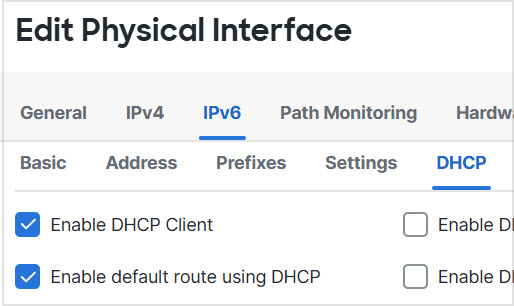
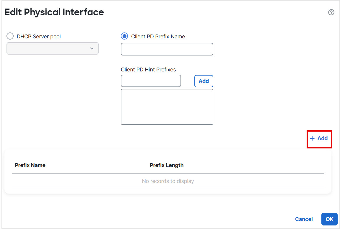
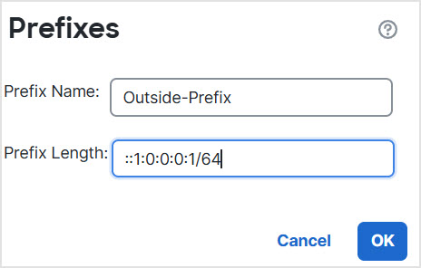
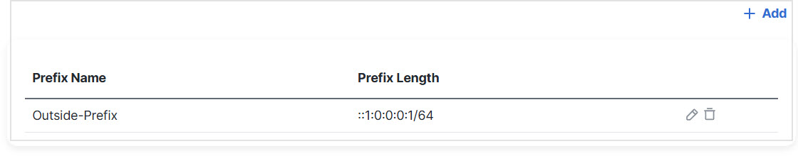
Step 7 | For Routed interfaces, you can optionally set the following values on the DHCP page:
|
Step 8 | For Routed interfaces, see Configure IPv6 neighbor discovery to configure settings on the Prefixes and Settings pages. For BVI interfaces, see the following parameters on the Settings page:
|
Step 9 | Click OK . Click Save. |

What to do next
Go to and deploy the policy to assigned devices. The changes are not active until you deploy them.