Configure automatic hardware bypass for power failure (ISA 3000)
Configure automatic hardware bypass to ensure network traffic continues to flow between interface pairs during power outages on ISA 3000 devices.
You can enable hardware bypass so that traffic continues to flow between an interface pair during a power outage. Supported interface pairs are copper interfaces GigabitEthernet 1/1 and 1/2; and GigabitEthernet 1/3 and 1/4. If you have a fiber Ethernet model, only the copper Ethernet pair (GigabitEthernet 1/1 and 1/2) supports hardware bypass.
When hardware bypass is active, traffic passes between these interface pairs at layer 1. The Firewall Threat Defense CLI will see the interfaces as being down. No firewall functions are in place, so make sure you understand the risks of allowing traffic to pass through the device.
In CLI Console or an SSH session, use the show hardware-bypass command to monitor the operational status.
Before you begin
For hardware bypass to work:
-
You must place the interface pairs in the same bridge group.
-
You must attach the interfaces to access ports on the switch. Do not attach them to trunk ports.
We recommend that you disable TCP sequence number randomization globally using the Threat Defense Service Policy attached to the access control policy assigned to the device. By default, the ISA 3000 rewrites the initial sequence number (ISN) of TCP connections passing through it to a random number. When hardware bypass is activated, the ISA 3000 is no longer in the data path and does not translate the sequence numbers. The receiving client receives an unexpected sequence number and drops the connection, so the TCP session needs to be re-established. Even with TCP sequence number randomization disabled, some TCP connections will have to be re-established because of the link that is temporarily down during the switchover.
Follow these steps to configure automatic hardware bypass for power failure:
Procedure
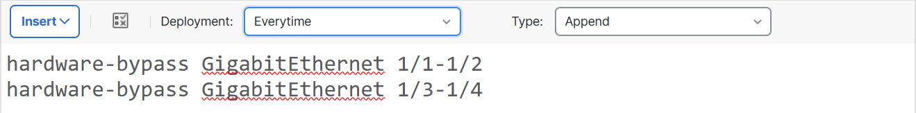
Step 1 | Create the FlexConfig object to enable automatic bypass.
|
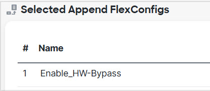
Step 2 | Create the FlexConfig policy and assign it to the devices.
|
Step 3 | Deploy your changes. Because you assigned a FlexConfig policy to the devices, you will always get a deployment warning, which is meant to caution you about the use of FlexConfig. Click Proceed to continue with the deployment. After the deployment completes, you can check the deployment history and view the transcript for the deployment. This is especially valuable if the deployment fails. See Verify the deployed configuration. |
What to do next
If you want to manually invoke hardware bypass or manually turn it off, you need to create two FlexConfig objects:
-
One that manually starts bypass, which would contain one or both of the following commands, depending on whether you want to invoke bypass for both pairs:
hardware-bypass manual GigabitEthernet 1/1-1/2 hardware-bypass manual GigabitEthernet 1/3-1/4 -
One that manually turns off bypass, which would contain one or both of the following commands:
no hardware-bypass manual GigabitEthernet 1/1-1/2
no hardware-bypass manual GigabitEthernet 1/3-1/4
You would then need to add one or the other object to the FlexConfig policy, and deploy changes, to either turn bypass on or off. You would also need to immediately remove the object from the FlexConfig policy after deployment. If you manually invoke bypass, you would then need to repeat the process to turn it off again. Thus, using this manual method requires frequent and careful editing of the FlexConfig policy and additional deployments.