Configure precision time protocol (ISA 3000)
The Precision Time Protocol (PTP) is a time-synchronization protocol developed to synchronize the clocks of various devices in a packet-based network. These device clocks are generally of varying precision and stability. The protocol is designed specifically for industrial, networked measurement and control systems, and is optimal for use in distributed systems because it requires minimal bandwidth and little processing overhead.
A PTP system is a distributed, networked system consisting of a combination of PTP and non-PTP devices. PTP devices include ordinary clocks, boundary clocks and transparent clocks. Non-PTP devices include network switches, routers and other infrastructure devices.
You can configure the Firewall Threat Defense device to be a transparent clock. The Firewall Threat Defense device does not synchronize its clock with the PTP clocks. The Firewall Threat Defense device will use the PTP default profile, as defined on the PTP clocks.
When you configure the PTP devices, you define a domain number for the devices that are meant to function together. Thus, you can configure multiple PTP domains, and then configure each non-PTP device to use the PTP clocks for one specific domain.
Before you begin
Determine the domain number configured on the PTP clocks that the device should use. This example assumes the PTP domain number is 10. Also, determine the interfaces through which the system can reach the PTP clocks in the domain.
These are the guidelines for configuring PTP.
-
This feature is only available on the Cisco ISA 3000 appliance.
-
Cisco PTP supports multicast PTP messages only.
-
PTP is available only for IPv4 networks, not for IPv6 networks.
-
PTP configuration is supported on physical Ethernet data interfaces, whether stand-alone or bridge group members. It is not supported on the management interface, subinterfaces, EtherChannels, Bridge Virtual Interfaces (BVI), or any other virtual interfaces.
-
PTP flows on VLAN subinterfaces are supported, assuming the appropriate PTP configuration is present on the parent interface.
-
You must ensure that PTP packets are allowed to flow through the device. PTP traffic is identified by UDP destination ports 319 and 320, and destination IP address 224.0.1.129, so any access control rule that allows this traffic should work.
-
In Routed firewall mode, you must enable multicast routing for PTP multicast groups. In addition, if an interface on which you enable PTP is not in a bridge group, you must configure the interface to join the IGMP multicast group 224.0.1.129. If the physical interface is a bridge group member, you do not configure it to join the IGMP multicast group.
Follow these steps to configure Precision Time Protocol on an ISA 3000 device:
Procedure
Step 1 | (Routed mode only) Enable Multicast routing, and configure the IGMP group for the interfaces. In Routed mode, you must enable Multicast routing. In addition, for stand-alone physical interfaces, that is, those that are not bridge group members, you must also configure the interface to join the 224.0.1.129 IGMP group. You cannot configure bridge group members to join an IGMP group, but PTP configuration on bridge group members will work without the IGMP join. Perform this procedure for each device on which you will configure PTP.
| ||
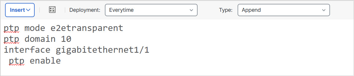
Step 2 | Create the FlexConfig object to enable PTP globally and on the interface. This procedure assumes that the PTP-clock-facing interface is the same on every device you are configuring. If you have used different interfaces on different devices, you need to create separate objects for each distinct combination. For example, if you use GigabitEthernet1/1 on devices A and B, GigabitEthernet1/2 on devices C and D, and both GigabitEthernet1/1 and 1/2 on devices E and F, you need 3 separate FlexConfig objects, and subsequently, 3 separate FlexConfig policies (explained in the next step).
| ||
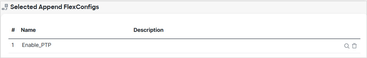
Step 3 | Create the FlexConfig policy and assign it to the devices. If you created multiple FlexConfig objects for different combinations of PTP-clock-facing interfaces, you need to create separate FlexConfig policies for each object, and assign those policies to the correct devices based on the interfaces you need to configure. Repeat this procedure for each group of devices.
| ||
Step 4 | Deploy your changes. Because you assigned a FlexConfig policy to the devices, you will always get a deployment warning, which is meant to caution you about the use of FlexConfig. Click Proceed to continue with the deployment. After the deployment completes, you can check the deployment history and view the transcript for the deployment. This is especially valuable if the deployment fails. See Verify the deployed configuration. | ||
Step 5 | Verify the PTP configuration on each device. From an SSH or Console session into each device, verify the PTP settings: |