Configure a VLAN Interface

This section describes how to configure VLAN interfaces for use with associated switch ports. By default, switch ports are assigned to VLAN1; however, you must manually add the logical VLAN1 interface (or whichever VLAN you set for these switch ports) for traffic to be routed and to participate in the threat defense security policy.

Procedure


Step 1

Select Devices > Device Management and click Edit (edit icon) for your threat defense device. The Interfaces page is selected by default.

Step 2

Click Add Interfaces > VLAN Interface.

Step 3

On General, set the following VLAN-specific parameters:

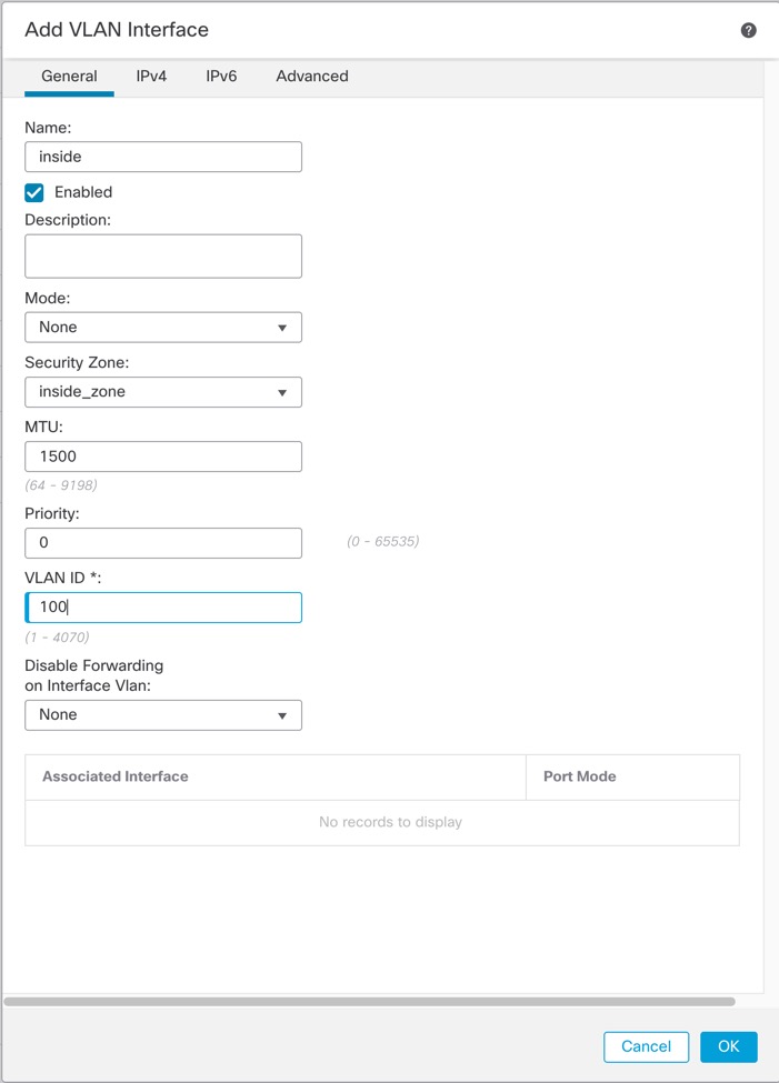
If you are editing an existing VLAN interface, the Associated Interface table shows switch ports on this VLAN.

  1. Set the VLAN ID, between 1 and 4070, excluding IDs in the range 3968 to 4047, which are reserved for internal use.

    You cannot change the VLAN ID after you save the interface; the VLAN ID is both the VLAN tag used, and the interface ID in your configuration.

  2. (Optional) Choose a VLAN ID for Disable Forwarding on Interface VLAN to disable forwarding to another VLAN.

    For example, you have one VLAN assigned to the outside for internet access, one VLAN assigned to an inside business network, and a third VLAN assigned to your home network. The home network does not need to access the business network, so you can disable forwarding on the home VLAN; the business network can access the home network, but the home network cannot access the business network.

Step 4

To complete the interface configuration, see one of the following procedures:

Step 5

Click OK.

Step 6

Click Save.

You can now go to Deploy > Deployment and deploy the policy to assigned devices. The changes are not active until you deploy them.