Configure switch ports as trunk ports
This task creates a trunk port that can carry multiple VLANs using 802.1Q tagging.
This procedure describes how to create a trunk port that can carry multiple VLANs using 802.1Q tagging. Trunk ports accept untagged and tagged traffic. Traffic on allowed VLANs pass through the trunk port unchanged.
When the trunk receives untagged traffic, it tags it to the native VLAN ID so that the Firewall Threat Defense device can forward the traffic to the correct switch ports or can route it to another firewall interface. When the Firewall Threat Defense device sends native VLAN ID traffic out of the trunk port, it removes the VLAN tag. Be sure to set the same native VLAN on the trunk port on the other switch so that the untagged traffic will be tagged to the same VLAN.
Procedure
Step 1 | Select and click Edit ( |
Step 2 | Click Edit ( 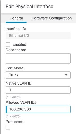
|
Step 3 | Enable the interface by checking the Enabled check box. |
Step 4 | (Optional) Add a description in the Description field. The description can be up to 200 characters on a single line, without carriage returns. |
Step 5 | Set the Port Mode to Trunk. |
Step 6 | Set the VLAN IDs: |
Step 7 | (Optional) Check the Protected check box to set this switch port as protected, so you can prevent the switch port from communicating with other protected switch ports on the same VLAN. You might want to prevent switch ports from communicating with each other if: the devices on those switch ports are primarily accessed from other VLANs; you do not need to allow intra-VLAN access; and you want to isolate the devices from each other in case of infection or other security breach. For example, if you have a DMZ that hosts three web servers, you can isolate the web servers from each other if you enable Protected on each switch port. The inside and outside networks can both communicate with all three web servers, and vice versa, but the web servers cannot communicate with each other. |
Step 8 | (Optional) Set the duplex and speed by clicking Hardware Configuration. 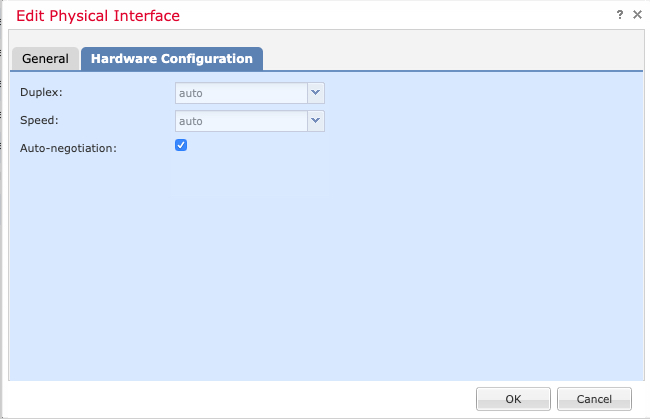
Check the Auto-negotiation check box (the default) to auto-detect the speed and duplex. If you uncheck it, you can set the speed and duplex manually:
If a peer switch connecting to the port over a 50G cable does not support auto-negotiation, ensure to disable auto-negotiation on the switch and the Threat Defense interface as well. For example, N9K-C93400LD-H1 does not support auto-negotiation on a 50G cable. Hence, you must disable the default auto-negotiation on the platform and the switch for the port to be connected. |
Step 9 | Click OK. Click Save. |
What to do next
Go to and deploy the policy to assigned devices. The changes are not active until you deploy them.