Add a Standalone Threat Defense for the Cisco Defense Orchestrator

You can use CDO with both native and container instances. Standalone logical devices work either alone or in a High Availability pair.

Before you begin

  • Download the application image you want to use for the logical device from Cisco.com, and then upload that image to the Firepower 4100/9300 chassis.

    Note

    For the Firepower 9300, you can install different application types (ASA and threat defense) on separate modules in the chassis. You can also run different versions of an application instance type on separate modules.

  • Configure a management interface to use with the logical device. The management interface is required. Note that this management interface is not the same as the chassis management port that is used only for chassis management (and that appears at the top of the Interfaces tab as MGMT).

  • You must also configure at least one Data type interface.

  • You must onboard the FTD device in CDO.

  • Gather the following information:

    • Interface IDs for this device

    • Management interface IP address and network mask

    • Gateway IP address

    • DNS server IP address

    • Threat Defense hostname and domain name

    • CDO onboard string

    • Threat Defense hostname and domain name

Procedure


Step 1

Choose Logical Devices.

Step 2

Click Add > Standalone, and set the following parameters:

  1. Provide a Device Name.

    This name is used by the chassis supervisor to configure management settings and to assign interfaces; it is not the device name used in the application configuration.

    Note

    You cannot change this name after you add the logical device.

  2. For the Template, choose Cisco Firepower Threat Defense.

  3. Choose the Image Version.

  4. Choose the Instance Type: Container or Native.

    A native instance uses all of the resources (CPU, RAM, and disk space) of the security module/engine, so you can only install one native instance. A container instance uses a subset of resources of the security module/engine, so you can install multiple container instances.

  5. Click OK.

    You see the Provisioning - device name window.

Step 3

Expand the Data Ports area, and click each interface that you want to assign to the device.

You can only assign data and data-sharing interfaces that you previously enabled on the Interfaces page. You will later enable and configure these interfaces in management center, including setting the IP addresses.

You can only assign up to 10 data-sharing interfaces to a container instance. Also, each data-sharing interface can be assigned to at most 14 container instances. A data-sharing interface is indicated by the sharing icon (sharing icon).

Hardware Bypass-capable ports are shown with the following icon: . For certain interface modules, you can enable the Hardware Bypass feature for Inline Set interfaces only (see the management center configuration guide). Hardware Bypass ensures that traffic continues to flow between an inline interface pair during a power outage. This feature can be used to maintain network connectivity in the case of software or hardware failures. If you do not assign both interfaces in a Hardware Bypass pair, you see a warning message to make sure your assignment is intentional. You do not need to use the Hardware Bypass feature, so you can assign single interfaces if you prefer.

Step 4

Click the device icon in the center of the screen.

A dialog box appears where you can configure initial bootstrap settings. These settings are meant for initial deployment only, or for disaster recovery. For normal operation, you can later change most values in the application CLI configuration.
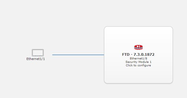
Step 5

On the General Information page, complete the following:
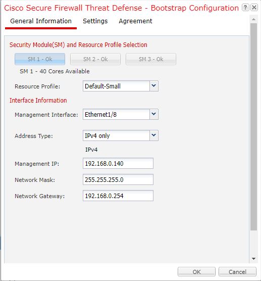
  1. (For the Firepower 9300) Under Security Module Selection click the security module that you want to use for this logical device.

  2. For a container instance, specify the Resource Profile.

    If you later assign a different resource profile, then the instance will reload, which can take approximately 5 minutes.

    Note

    If you later assign a different profile to instances in an established high-availability pair, which requires the profile to be the same on both units, you must:

    1. Break high availability.

    2. Assign the new profile to both units.

    3. Re-establish high availability.

  3. Choose the Management Interface.

    This interface is used to manage the logical device. This interface is separate from the chassis management port.

  4. Choose the management interface Address Type: IPv4 only, IPv6 only, or IPv4 and IPv6.

  5. Configure the Management IP address.

    Set a unique IP address for this interface.

  6. Enter a Network Mask or Prefix Length.

  7. Enter a Network Gateway address.

Step 6

On the Settings tab, complete the following:
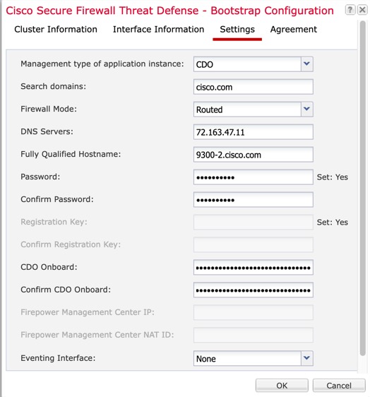
Settings
Settings
  1. In the Management type of application instance drop-down list, choose CDO.

  2. Enter the Search Domains as a comma-separated list.

  3. Choose the Firewall Mode: Transparent or Routed.

  4. Enter the DNS Servers as a comma-separated list.

  5. Enter the Fully Qualified Hostname for the threat defense.

  6. Enter a Password for the threat defense admin user for CLI access.

  7. Re-enter the password in Confirm Password for the threat defense admin user for CLI access

  8. Enter the CDO Onboard command string for the threat defense.

    CDO generates an onboarding command string once you onboard your FTD. Copy that string and place it in the CDO Onboard field.

    For example:

    
    configure manager add cisco-sapphire.app.staging.cdo.cisco.com TuNDBm6peReVDbUkOpZCgtJ1GqWKbD30
    o9B064UXEwmr3AYAEpuflf4qE2E3JKY5 cisco-sapphire.app.staging.cdo.cisco.com
    
  9. Re-enter the command string in Confirm CDO Onboard.

  10. A separate Eventing Interface is not supported for CDO, so this setting will be ignored.

Step 7

On the Agreement tab, read and accept the end user license agreement (EULA).
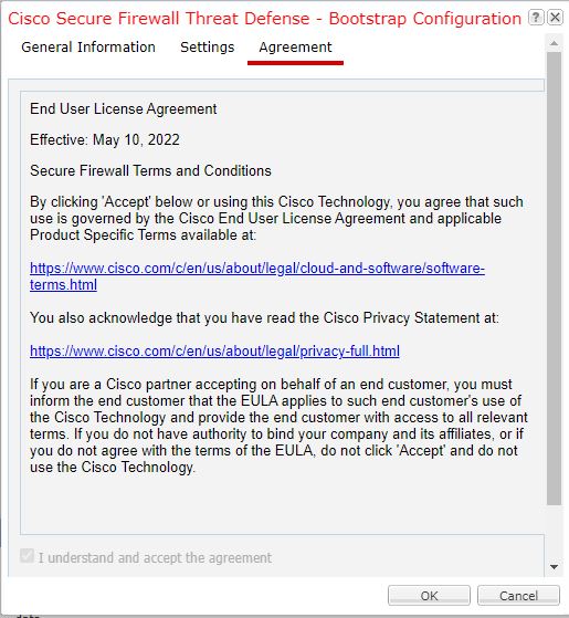
Step 8

Click OK to close the configuration dialog box.

Step 9

Click Save.

The chassis deploys the logical device by downloading the specified software version and pushing the bootstrap configuration and management interface settings to the application instance. Check the Logical Devices page for the status of the new logical device. When the logical device shows its Status as online, you can start configuring the security policy in the application.
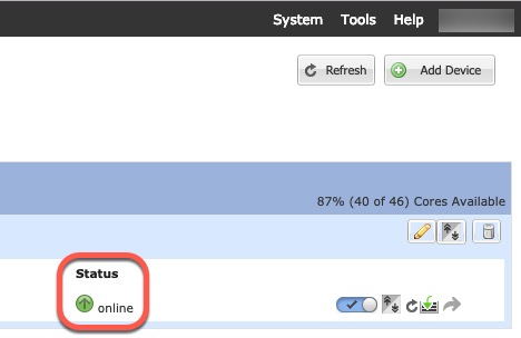
Step 10

Save the configuration.

commit-buffer

The chassis deploys the logical device by downloading the specified software version and pushing the bootstrap configuration and management interface settings to the application instance. Check the status of the deployment using the show app-instance command. The application instance is running and ready to use when the Admin State is Enabled and the Oper State is Online.

Example:


Firepower /ssa/logical-device* # commit-buffer
Firepower /ssa/logical-device # exit
Firepower /ssa # show app-instance
App Name   Identifier Slot ID    Admin State Oper State       Running Version Startup Version Deploy Type Profile Name Cluster State   Cluster Role
---------- ---------- ---------- ----------- ---------------- --------------- --------------- ----------- ------------ --------------- ------------
asa        asa1       2          Disabled    Not Installed                    9.12.1          Native                   Not Applicable  None
ftd        ftd1       1          Enabled     Online           7.3.0            7.3.0        Container   Default-Small Not Applicable  None

Step 11

See the CDO configuration guide to start configuring your security policy.