Configure Multiple Hubs in a Route-based VPN

You can configure a topology with multiple hubs for a set of spokes. With one hub as the backup hub, you can configure multiple topologies with a single hub and the same set of spokes.
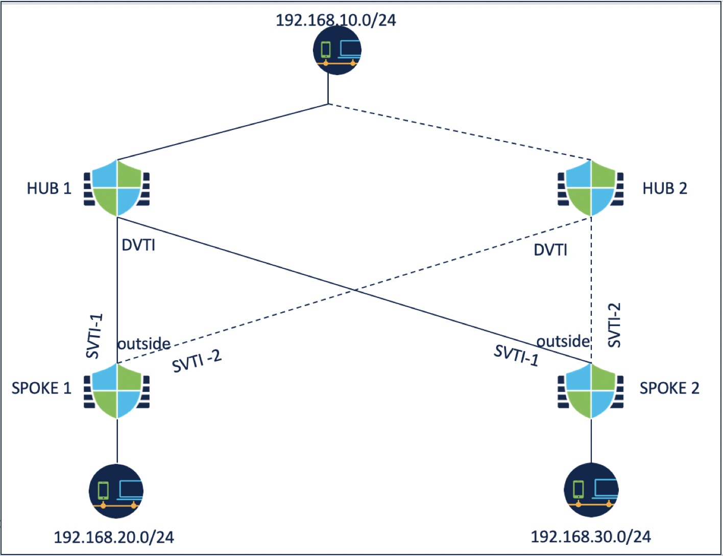
In the following example, there are two hubs connected to the same set of spokes. Hub 1 is the primary hub and Hub 2 is the secondary hub. To configure this network in the management center, you must configure two route-based hub and spoke topologies:

  • Topology 1: Hub 1 connected to spoke 1 and spoke 2.

  • Topology 2: Hub 2 connected to spoke 1 and spoke 2.

To configure topology 1:

Procedure


Step 1

Choose Devices > Site To Site and click + Site To Site VPN.

Step 2

Enter a name for the VPN topology in the Topology Name field.

Step 3

Choose Route Based (VTI) > Hub and Spoke > Endpoints.

Step 4

Under Hub Nodes:

  1. Click + to add the hub.

  2. Choose Hub 1 from the Device drop-down list.

  3. Choose a dynamic VTI from the Dynamic Virtual Tunnel Interface drop-down list or click + to add a new dynamic VTI.

    We recommend that you configure the Borrow IP for the dynamic interface from a loopback interface.

  4. (Optional) If your endpoint device is behind a NAT device, check the Tunnel Source IP is Private check box and configure the tunnel source IP address in the Tunnel Source Public IP Address field.

  5. Click Routing Policy to configure the routing policy for the hub. You can configure dynamic routing using BGP.

  6. Expand Advance Settings. You can configure the following advanced settings for the hub to enable IKEv2 routing, which can be used if you do not use dynamic routing.

    • (Optional) Check the Send Virtual Tunnel Interface IP to the peers check box.

    • Check the Allow incoming IKEv2 routes from the peers check box for the hub to accept routes from the spokes and update the routing table.

    • Choose Connection Type as Bidirectional from the drop-down list.

  7. Click OK.

Step 5

Under Spoke Nodes:

  1. Click + to add a spoke.

  2. Choose Spoke 1 from the Device drop-down list.

  3. Choose SVTI-1 as the static VTI for the spoke from the Static Virtual Tunnel Interface drop-down list or click + to add a new static VTI.

    Choose the outside interface as the tunnel source of SVTI-1. Tunnel IP of SVTI-1 is autopopulated, ensure that this IP address is unique for spoke 1 across peers in both the topologies.

  4. Expand Advance Settings. If you do not use dynamic routing, you can configure these settings to enable IKEv2 routing for the spoke.

    • Check the Send Virtual Tunnel Interface IP to the peers check box to send the VTI IP address to the peer device.

    • Check the Allow incoming IKEv2 routes from the peers check box to allow incoming IKEv2 routes from the peers.

    • Choose Connection Type as Bidirectional from the drop-down list.

  5. Click OK.

  6. Repeat steps 5a to 5e to add spoke 2. Configure SVTI-1 as the static VTI of spoke 2.

Step 6

Configure the IKE and IPSec parameters as required or use the default values.


What to do next

  1. Repeat steps 3 to 6 to configure topology 2 with hub 2, spoke 1, and spoke 2.

    Configure SVTI-2 as the static VTI of spoke 1 and SVTI-2 as the static VTI of spoke 2 (refer the above illustration). Tunnel source for SVTI-2 should be the same outside interface.

  2. For each spoke, configure the routing policy. For more information, see Configure Routing for Multiple Hubs in a Route-based VPN.

  3. Verify the configuration and tunnel statuses. For more information, see Verify the Multiple Hubs Configuration in a Route-based VPN.