Configure a Physical Interface
You can physically enable and disable interfaces, as well as set the interface speed and duplex and other hardware settings. To use an interface, it must be physically enabled for the chassis and logically enabled in the instance. By default, physical interfaces are disabled. For VLAN subinterfaces, the admin state is inherited from the parent interface.
Procedure
Step 1 | From , click Manage in the Chassis column or click Edit ( 
The Chassis Manager page opens for the chassis to the Summary page. | ||
Step 2 | Click Interfaces. 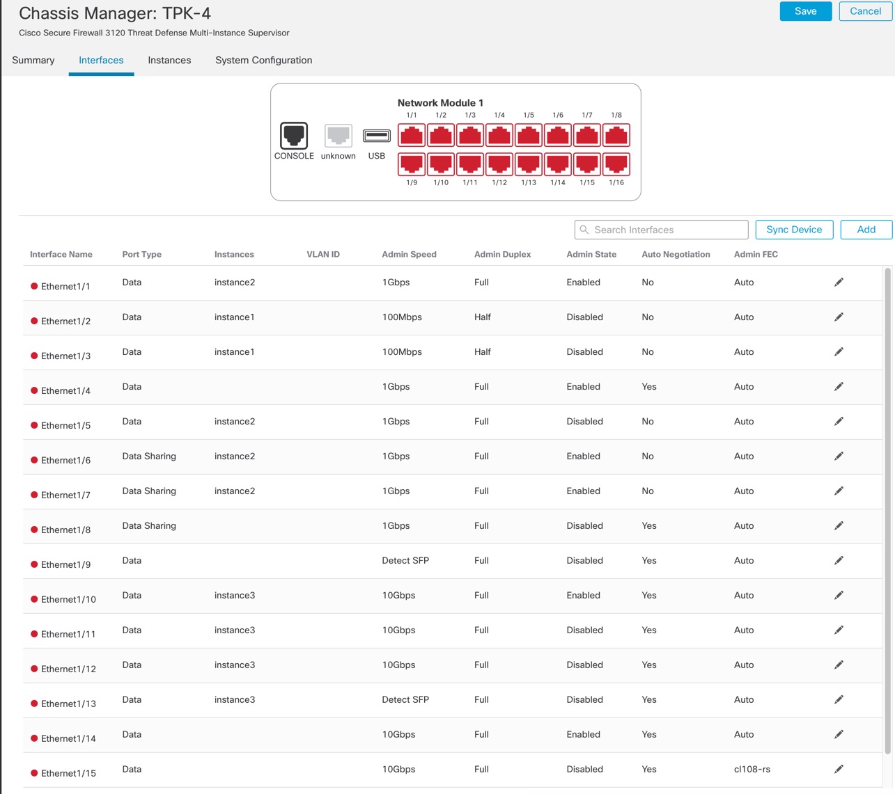
| ||
Step 3 | Click Edit ( 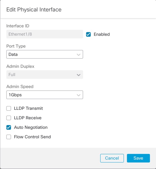
| ||
Step 4 | Enable the interface by checking the Enabled check box. | ||
Step 5 | For the Port Type, choose Data or Data Sharing. 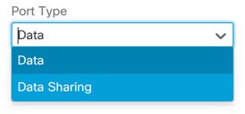
| ||
Step 6 | Set the Admin Duplex. Speeds of 1Gbps and higher only support Full duplex. SFP interfaces only support Full duplex. | ||
Step 7 | Set the Admin Speed. For SFPs, Choose Detect SFP to detect the speed of the installed SFP module and use the appropriate speed. Duplex is always Full, and auto-negotiation is always enabled. This option is useful if you later change the network module to a different model, and want the speed to update automatically. | ||
Step 8 | (Optional) Check Flow Control Send to enable pause (XOFF) frames for flow control. Flow control enables connected Ethernet ports to control traffic rates during congestion by allowing congested nodes to pause link operation at the other end. If the threat defense port experiences congestion (exhaustion of queuing resources on the internal switch) and cannot receive any more traffic, it notifies the other port by sending a pause frame to stop sending until the condition clears. Upon receipt of a pause frame, the sending device stops sending any data packets, which prevents any loss of data packets during the congestion period.
The internal switch has a global pool of 8000 buffers of 250 bytes each, and the switch allocates buffers dynamically to each port. A pause frame is sent out every interface with flow control enabled when the buffer usage exceeds the global high-water mark (2 MB (8000 buffers)); and a pause frame is sent out of a particular interface when its buffer exceeds the port high-water mark (.3125 MB (1250 buffers)). After a pause is sent, an XON frame can be sent when the buffer usage is reduced below the low-water mark (1.25 MB globally (5000 buffers); .25 MB per port (1000 buffers)). The link partner can resume traffic after receiving an XON frame. Only flow control frames defined in 802.3x are supported. Priority-based flow control is not supported. | ||
Step 9 | (Optional) Check Auto Negotiation to set the interface to negotiate the speed, link status, and flow control. You cannot edit this setting for speeds lower than 1Gbps. For SFP interfaces, you can only disable auto-negotiation when the speed is set to 1Gbps. | ||
Step 10 | Click Save and then Save in the top right of the Interfaces page. You can now Deploy the policy to the chassis. The changes are not active until you deploy them. |