You can easily deploy the cluster from the Firepower 4100/9300 chassis supervisor. All initial configuration is automatically generated for each unit.
For clustering on
multiple chassis, you must configure each chassis separately. Deploy the cluster on
one chassis; you can then copy the bootstrap configuration from the first chassis to
the next chassis for ease of deployment.
In a Firepower 9300 chassis, you must enable clustering for all 3 module slots, or for container instances, a container instance in each slot, even if you do not have a module installed. If you do not configure all 3 modules, the cluster will not come up.
Before you begin
Download the application image you want to use for the logical device from Cisco.com, and then upload that image to the Firepower 4100/9300 chassis.
For container instances, before you can install a container instance for the first time, you must reinitialize the security module/engine so that the disk has the correct formatting. Choose Security Modules or Security Engine, and click the Reinitialize icon (). An existing logical device will be deleted and then reinstalled as a new device, losing any local application configuration. If you are replacing a native instance with container instances, you will need to delete the native instance in any case. You cannot automatically migrate a native instance to a container instance.
Gather the following information:
Management interface ID, IP addresses, and network mask
Gateway IP address
Firewall Management Center IP address and/or NAT ID of your choosing
For clustering on
multiple chassis, all data interfaces must be Spanned EtherChannels
with at least one member interface. Add the same EtherChannels on
each chassis. Combine the member interfaces from all cluster units
into a single EtherChannel on the switch. See Clustering Guidelines and Limitations for more information about
EtherChannels.
For multi-instance clustering,
you cannot use FXOS-defined VLAN subinterfaces or data-sharing
interfaces in the cluster. Only application-defined subinterfaces
are supported. See FXOS Interfaces vs. Application Interfaces for more
information.
The management interface is required. Note that this management interface is not the same as the chassis management interface that is used only for chassis management (in FXOS, you might see the chassis management interface displayed as MGMT, management0, or other similar names).
For clustering on multiple
chassis, add the same Management interface on each chassis.
For multi-instance clustering, you can share the same management interface across multiple clusters on the same chassis, or with standalone instances.
For
clustering on multiple chassis, add a member interface to the cluster
control link EtherChannel (by default, port-channel 48). See Add an EtherChannel (Port Channel).
Do not add a member interface for a cluster isolated to security
modules within one Firepower 9300 chassis. If you add a member, the
chassis assumes this cluster will be using multiple chassis, and
will only allow you to use Spanned EtherChannels, for example.
On the
Interfaces tab, the port-channel 48
cluster type interface shows the Operation
State as failed if it does
not include any member interfaces. For a cluster isolated to
security modules within one Firepower 9300 chassis, this
EtherChannel does not require any member interfaces, and you can
ignore this Operational State.
Add the same member interfaces on each chassis. The cluster control
link is a device-local EtherChannel on each chassis. Use separate
EtherChannels on the switch per device. See Clustering Guidelines and Limitations for more information about
EtherChannels.
For multi-instance clustering,
you can create additional Cluster type EtherChannels. Unlike the
Management interface, the cluster control link is not
sharable across multiple devices, so you will need a Cluster
interface for each cluster. However, we recommend using VLAN
subinterfaces instead of multiple EtherChannels; see the next step
to add a VLAN subinterface to the Cluster interface.
This interface is a secondary management interface for the Firewall Threat Defense devices. To use this interface, you must configure its IP address and other parameters at the Firewall Threat Defense CLI. For example, you can separate management traffic from events (such as web events). See the configure network commands in the Firewall Threat Defense command reference.
For clustering on
multiple chassis, add the same eventing interface on each chassis.
Step 2
Choose Logical Devices.
Step 3
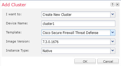
Click Add > Cluster, and set the following parameters:
Native ClusterMulti-Instance Cluster
Choose I want to: > Create New Cluster
Provide a Device Name.
This name is used internally by the chassis supervisor to configure
management settings and to assign interfaces; it is not the device
name used in the application configuration.
For the Template, choose Cisco Firepower Threat
Defense.
Choose the Image Version.
For the Instance Type, choose either Native or Container.
A native instance uses all of the resources (CPU, RAM, and disk space) of the security module/engine, so you can only install one native instance. A container instance uses a subset of resources of the security module/engine, so you can install multiple container instances.
(Container Instance only) For the Resource Type, choose one of the resource profiles from the drop-down list.
For the Firepower 9300, this profile will be applied to each instance on each security module. You can set different profiles per security module later in this procedure; for example, if you are using different security module types, and you want to use more CPUs on a lower-end model. We recommend choosing the correct profile before you create the cluster. If you need to create a new profile, cancel out of the cluster creation, and add one using Add a Resource Profile for Container Instances.
Note
If you assign a different profile to instances in an established
cluster, which allows mismatched profiles, then apply the new
profile on the data nodes first; after they reboot and come back
up, you can apply the new profile to the control node.
Click the Create New Cluster radio button.
Click OK.
You see the Provisioning - device name window.
Step 4
Choose the interfaces you want to assign to this cluster.
For native mode clustering:
All valid interfaces are assigned by default. If you defined multiple Cluster
type interfaces, deselect all but one.
For multi-instance clustering: Choose each data
interface you want to assign to the cluster, and also choose the Cluster type
port-channel or port-channel subinterface.
Step 5
Click the device icon in the center of the screen.
A dialog box appears where you can configure initial bootstrap settings. These settings are meant for initial deployment only, or for disaster recovery. For normal operation, you can later change most values in the application CLI configuration.
Step 6
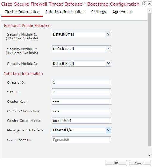
On the Cluster Information page, complete the following.
Native ClusterMulti-Instance Cluster
(Container Instance for the Firepower 9300 only) In the Security Module (SM) and Resource Profile Selection area, you can set a different resource profile per module; for example, if you are using different security module types, and you want to use more CPUs on a lower-end model.
For clustering on multiple
chassis, in the Chassis ID field, enter a chassis
ID. Each chassis in the cluster must use a unique ID.
This field only appears if you added a member interface to cluster
control link Port-Channel 48.
For inter-site clustering, in the Site ID field, enter the
site ID for this chassis between 1 and 8. FlexConfig feature. Additional inter-site
cluster customizations to enhance redundancy and stability, such as director
localization, site
redundancy, and cluster flow mobility, are only configurable using the Firewall Management Center FlexConfig feature.
In the Cluster Key field, configure an authentication key for control traffic on the cluster control link.
The shared secret is an ASCII string from 1 to 63 characters. The shared secret is used to generate the key. This option does not affect datapath traffic, including connection state update and forwarded packets, which are always sent in the clear.
Set the Cluster Group Name, which is the cluster group name in the logical device configuration.
The name must be an ASCII string from 1 to 38 characters.
Important
From 2.4.1, spaces in cluster group name will be considered as special characters and may result in error while deploying the logical devices. To avoid this issue, you must rename the cluster group name without a space.
Choose the Management Interface.
This interface is used to manage the logical device. This interface is separate
from the chassis management port.
If you assign a Hardware Bypass-capable interface as the Management interface, you see a warning message to make
sure your assignment is intentional.
Step 7
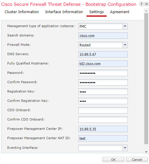
On the Settings page, complete the following.
In the Registration Key field, enter the key to be shared between the Firewall Management Center and the cluster members during registration.
You can choose any text string for this key between 1 and 37 characters; you will enter the same key on the Firewall Management Center when you add the Firewall Threat Defense.
Enter a Password for the Firewall Threat Defense admin user for CLI access.
In the Firepower Management Center IP field, enter the IP address of the managing Firewall Management Center. If you do not know the Firewall Management Center IP address, leave this field blank and enter a passphrase in the Firepower Management Center NAT ID field.
(Optional) For a container instance, Permit Expert mode from FTD SSH
sessions: Yes or No.
Expert Mode provides Firewall Threat Defense shell access for advanced troubleshooting.
If you choose Yes for this option, then users who access the
container instance directly from an SSH sesssion can enter Expert Mode. If you
choose No, then only users who access the container instance
from the FXOS CLI can enter Expert Mode. We recommend choosing
No to increase isolation between instances.
Use Expert Mode only if a documented procedure tells you it is required, or if the
Cisco Technical Assistance Center asks you to use it. To enter this mode, use the
expert command in the Firewall Threat Defense CLI.
(Optional) In the Search Domains field, enter a comma-separated list of
search domains for the management network.
(Optional) From the Firewall Mode drop-down list, choose
Transparent or Routed.
In routed mode, the Firewall Threat Defense is considered to be a router hop in the network. Each interface that you want to
route between is on a different subnet. A transparent firewall, on the other hand,
is a Layer 2 firewall that acts like a “bump in the wire,” or a “stealth firewall,”
and is not seen as a router hop to connected devices.
The firewall mode is only set at initial deployment. If you re-apply the bootstrap
settings, this setting is not used.
(Optional) In the DNS Servers field, enter a comma-separated list of
DNS servers.
The Firewall Threat Defense uses DNS if you specify a hostname for the Firewall Management Center, for example.
(Optional) In the Firepower Management Center NAT ID field, enter a passphrase that you will also enter on the Firewall Management Center when you add the cluster as a new device.
Normally, you need both IP addresses (along with a registration key) for both routing purposes and for authentication: the Firewall Management Center specifies the device IP address, and the device specifies the Firewall Management Center IP address. However, if you only know one of the IP addresses, which is the minimum requirement for routing purposes, then you must also specify a unique NAT ID on both sides of the connection to establish trust for the initial communication and to look up the correct registration key. You can specify any text string as the NAT ID, from 1 to 37 characters. The Firewall Management Center and device use the registration key and NAT ID (instead of IP addresses) to authenticate and authorize for initial registration.
(Optional) In the Fully Qualified Hostname field, enter a fully
qualified name for the Firewall Threat Defense device.
Valid characters are the letters from a to z, the digits from 0 to 9, the dot (.),
and the hyphen (-); maximum number of characters is 253.
(Optional) From the Eventing Interface drop-down list, choose the interface on which events should be sent. If not specified, the management interface will be used.
To specify a separate interface to use for events, you must configure an interface as a firepower-eventing interface. If you assign a Hardware Bypass-capable interface as the Eventing interface, you see a warning message to make sure your assignment is intentional.
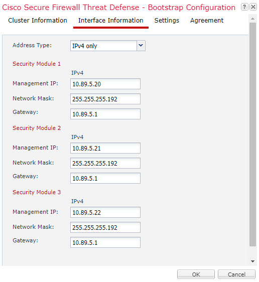
Step 8
On the Interface Information page, configure a management IP address for each security module in the cluster. Select the type of address from the Address Type drop-down list and then complete the following for each security module.
Note
You must set the IP address for all 3 module slots in a chassis, even if you do not
have a module installed. If you do not configure all 3 modules, the cluster will not
come up.
In the Management IP field, configure an IP address.
Specify a unique IP address on the same network for each module.
Enter a Network Mask or Prefix Length.
Enter a Network Gateway address.
Step 9
On the Agreement tab, read and accept the end user license agreement (EULA).
Step 10
Click OK to close the configuration dialog box.
Step 11
Click Save.
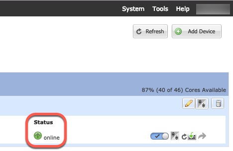
The chassis deploys the logical device by downloading the specified software version and
pushing the bootstrap configuration and management interface settings to the
application instance. Check the Logical Devices page
for the status of the new logical device. When the logical device shows its
Status as online, you can
add
the remaining cluster chassis, or for a cluster isolated to security
modules within one Firepower 9300 chassis, start configuring the
cluster in the application. You may see the "Security module not responding"
status as part of the process; this status is normal and is
temporary.
Step 12
For clustering on multiple chassis, add the next
chassis to the cluster:
On the first chassis of the Firewall Chassis Manager, click the Show Configuration
icon
at the top right; copy the displayed cluster configuration.
Connect to the Firewall Chassis Manager on the next chassis, and add a logical device according to this
procedure.
Choose I want to: > Join an Existing
Cluster.
Click
OK.
In the Copy Cluster Details box, paste in the
cluster configuration from the first chassis, and click
OK.
Click the device icon in the center of the screen. The cluster information is
mostly pre-filled, but you must change the following settings:
Chassis ID—Enter a unique chassis ID.
Site ID—For inter-site clustering, enter the site ID for
this chassis between 1 and 8. Additional inter-site cluster customizations to
enhance redundancy and stability, such as director localization, site redundancy, and
cluster flow mobility, are only configurable using the Firewall Management Center FlexConfig feature.
Cluster Key—(Not prefilled) Enter the same cluster key.
Management IP—Change the management address for each
module to be a unique IP address on the same network as the other cluster
members.
Click OK.
Click Save.
The chassis deploys the logical device by downloading the specified
software version and pushing the bootstrap configuration and
management interface settings to the application instance. Check the
Logical Devices page for each cluster
member for the status of the new logical device. When the logical
device for each cluster member shows its
Status as online,
you can start configuring the cluster in the application. You may
see the "Security module not responding" status as part of the
process; this status is normal and is temporary.
Step 13
Add each unit separately to the Firewall Management Center using the management IP addresses, and then group them into a cluster at the web interface.
All cluster units must be in a successfully-formed cluster on FXOS prior to adding them to Firewall Management Center.
 ). An existing logical device will be deleted and then reinstalled as a new device, losing any local application configuration. If you are replacing a native instance with container instances, you will need to delete the native instance in any case. You cannot automatically migrate a native instance to a container instance.