Create a Cluster
Form a cluster from one or more devices in the Cloud-Delivered Firewall Management Center.
Before you begin
Some features are not compatible with clustering, so you should wait to perform configuration until after you enable clustering. Some features will block cluster creation if they are already configured. For example, do not configure any IP addresses on interfaces, or unsupported interface types such as BVIs.
Procedure
Step 1 | Choose , and then choose . The Add Cluster Wizard appears. 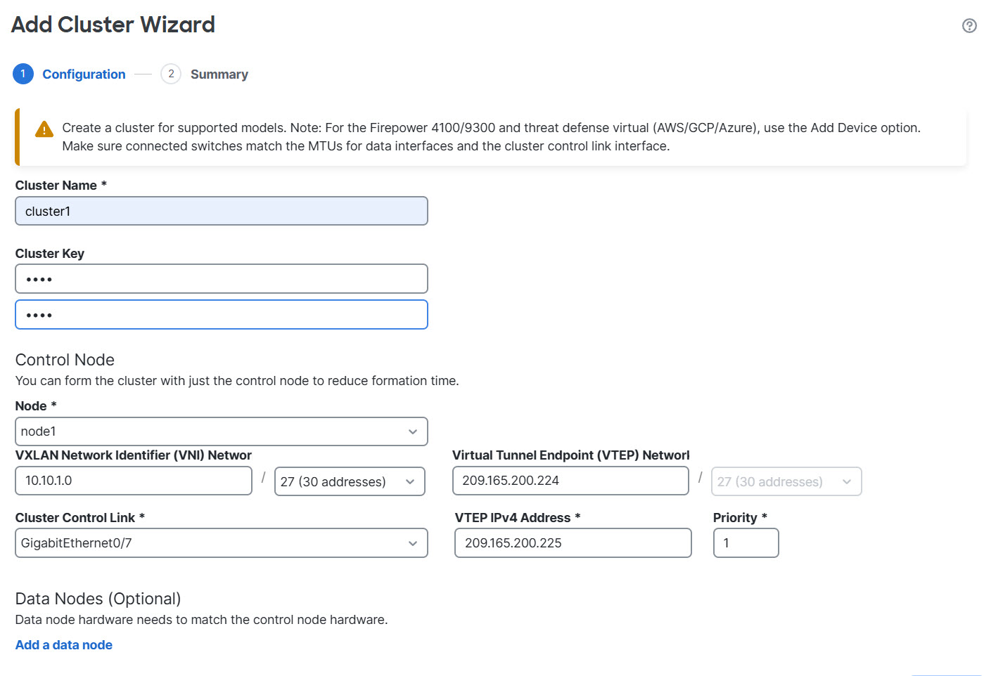
| ||
Step 2 | Specify a Cluster Name and an authentication Cluster Key for control traffic.
| ||
Step 3 | For the Control Node, set the following:
| ||
Step 4 | For Data Nodes (Optional), click Add a data node to add a node to the cluster. You can form the cluster with only the control node for faster cluster formation, or you can add all nodes now. Set the following for each data node:
| ||
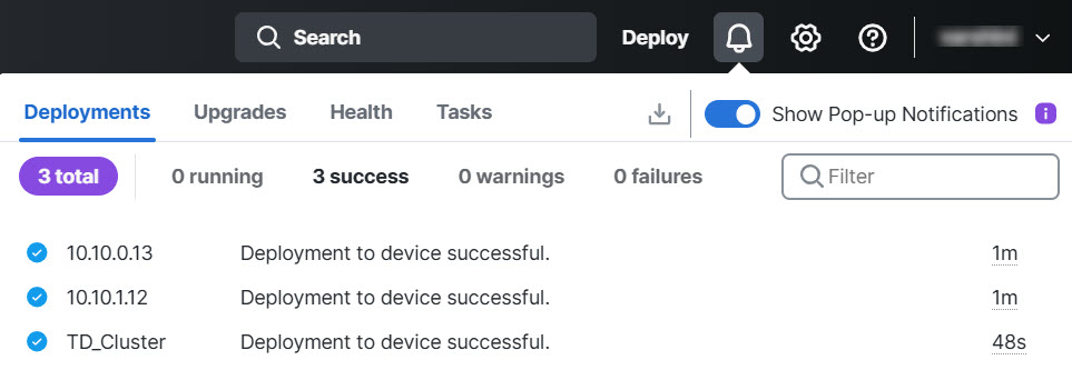
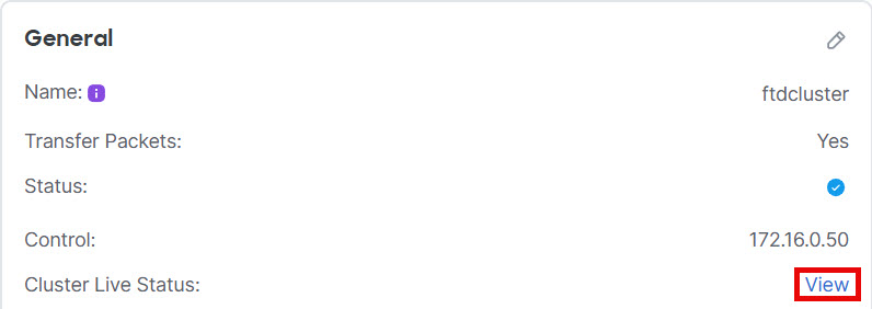
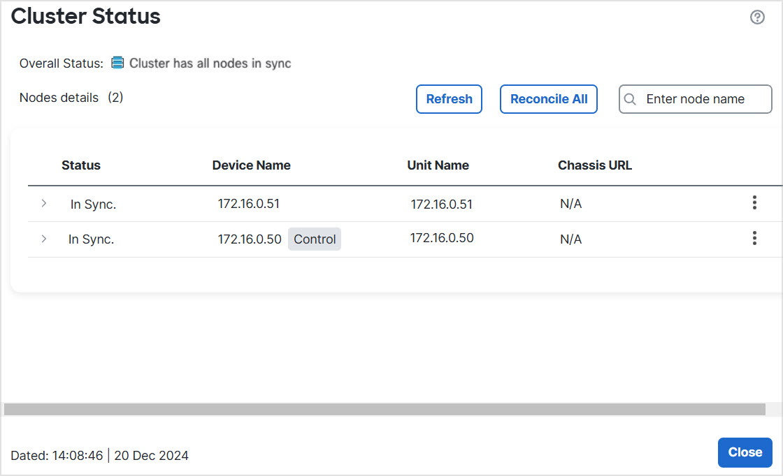
Step 5 | Click Continue. Review the Summary, and then click Save. The cluster bootstrap configuration is saved to the cluster nodes. The bootstrap configuration includes the VXLAN interface used for the cluster control link. The cluster name shows on the page; expand the cluster to see the cluster nodes. 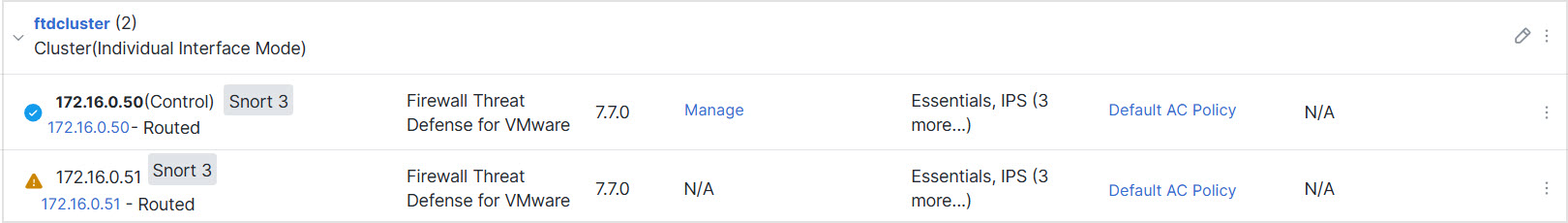
A node that is currently registering shows the loading icon. 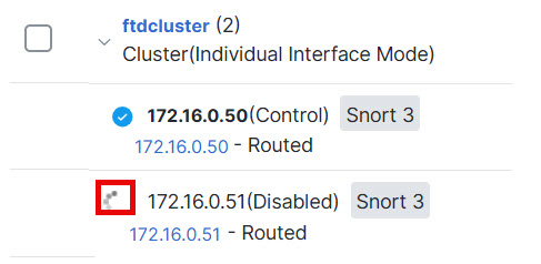
| ||
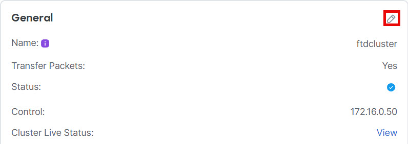
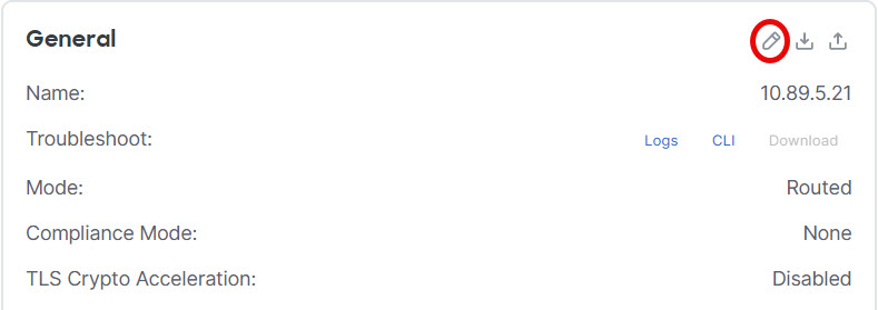
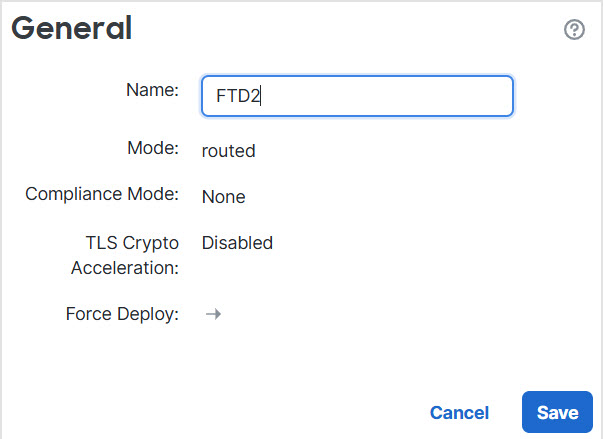
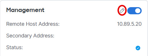
Step 6 | Configure device-specific settings by clicking the Edit ( Most configuration can be applied to the cluster as a whole, and not nodes in the cluster. For example, you can change the display name per node, but you can only configure interfaces for the whole cluster. | ||
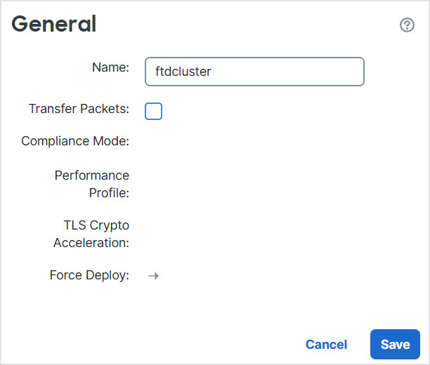
Step 7 | On the , screen, you see General and other settings for the cluster. 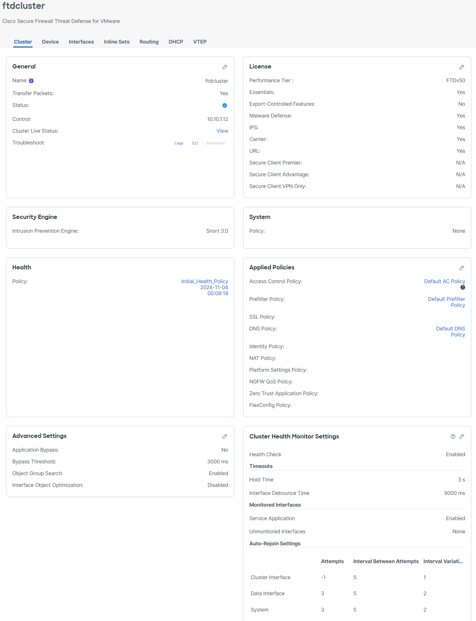
| ||
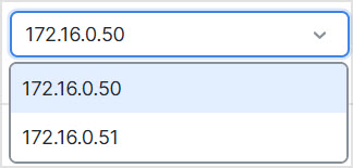
Step 8 | On the and then click , you can choose each member in the cluster from the top right drop-down menu and configure the following settings. 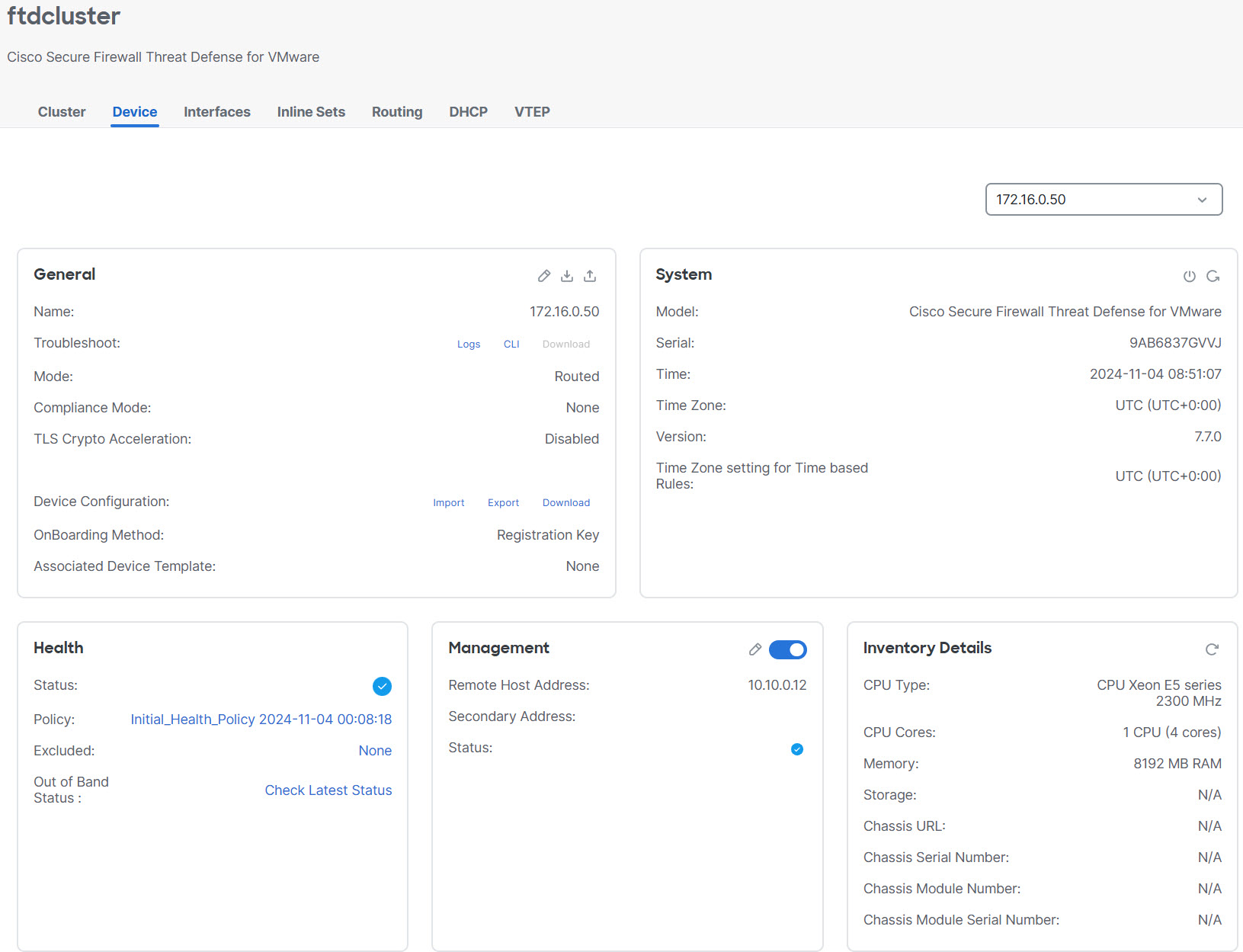
| ||
Step 9 | If you deployed your cluster nodes without enabling jumbo-frame reservation, then restart all cluster nodes to enable jumbo frames, which are required for the cluster control link. See Shut down or restart the device. If you previously enabled jumbo-frame reservation, you can skip this step. Because the cluster control link traffic includes data packet forwarding, the cluster control link needs to accommodate the entire size of a data packet plus cluster traffic overhead (100 bytes) and VXLAN overhead (54 bytes). When you create the cluster, the MTU is set to 154 bytes higher than the highest data interface MTU (1654 by default). If you later increase the data interface MTU, be sure to also increase the cluster control link MTU. For example, because the maximum MTU is 9198 bytes, then the highest data interface MTU can be 9044, while the cluster control link can be set to 9198. See Configure the MTU. Make sure you configure switches connected to the cluster control link to the correct (higher) MTU; otherwise, cluster formation might fail. |