How to Provide Internet Access with Overlapping Address Spaces

When using virtual routers, you can have the same network address for interfaces that reside in separate routers. However, because the IP addresses routed in these separate virtual routers are the same, apply NAT/PAT rules for each interface with separate NAT/PAT pools to ensure that return traffic goes to the correct destination. This example provides the procedure to configure the virtual routers and NAT/PAT rules to manage the overlapping address spaces.

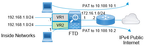
For example, interfaces vr1-inside and vr2-inside on threat defense is defined to use the IP address 192.168.1.1/24, managing endpoints on their segment in the 192.168.1.0/24 network. To allow Internet access from two virtual routers that use the same address space, you need to apply NAT rules separately to the interfaces within each virtual router, ideally using separate NAT or PAT pools. You could use PAT to translate the source addresses in VR1 to 10.100.10.1, and for those in VR2, to 10.100.10.2. The following illustration shows this setup, where the Internet-facing outside interface is part of the global router. You must define the NAT/PAT rules with the source interface (vr1-inside and vr2-inside) explicitly selected—using “any” as the source interface makes it impossible for the system to identify the correct source because the same IP address could exist on two different interfaces.

Network diagram for overlapping address space
Note

Even if you have some interfaces within virtual routers that does not use overlapping address spaces, define the NAT rule with the source interface to make troubleshooting easier, and to ensure a cleaner separation between traffic from the virtual routers that is Internet-bound.

Procedure


Step 1

Configure the inside interface of the device for VR1:

  1. Choose Devices > Device Management > Interfaces.

  2. Edit the interfaces that you want to assign to VR1:

    • Name—For this example, vr1-inside.

    • Select the Enabled checkbox.

    • In IPV4, for IP Type, choose Use Static IP.

    • IP Address—Enter 192.168.1.1/24.

  3. Click Ok.

  4. Click Save.

Step 2

Configure the inside interface of the device for VR2:
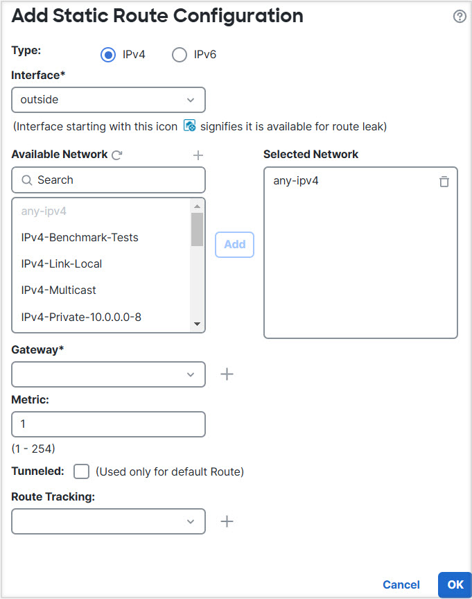
  1. Choose Devices > Device Management > Interfaces.

  2. Edit the interfaces that you want to assign to VR2:

    • Name—For this example, vr2-inside.

    • Select the Enabled checkbox.

    • In IPV4, for IP Type, choose Use Static IP.

    • IP Address—Leave it blank. The system does not allow you to configure interfaces with same IP address, as you are yet to create user-defined virtual routers.

  3. Click Ok.

  4. Click Save.

Step 3

Configure VR1 and the static default route leak to the outside interface:

  1. Choose Devices > Device Management, and edit the threat defense device.

  2. Choose Routing > Manage Virtual Routers. Click Add Virtual Router and create VR1.

  3. For VR1, in Virtual Router Properties, assign vr1-inside and save.

  4. Click Static Route.

  5. Click Add Route. In Add Static Route Configuration, specify the following:

    • Interface—Select the outside interface of the global router.

    • Network—Select the any-ipv4 object. This network is the default route for any traffic that cannot be routed within VR1.

    • Gateway—Leave it blank. When leaking a route into another virtual router, do not provide a Gateway.

  6. Click Ok.

  7. Click Save.

Step 4

Configure VR2 and the static default route leak to the outside interface:

  1. Choose Devices > Device Management, and edit the threat defense device.

  2. Choose Routing > Manage Virtual Routers. Click Add Virtual Router and create VR2.

  3. For VR2, in Virtual Router Properties, assign vr2-inside and save.

  4. Click Static Route.

  5. Click Add Route. In Add Static Route Configuration, specify the following:

    • Interface—Select the outside interface of the global router.

    • Network—Select the any-ipv4 object. This network is the default route for any traffic that cannot be routed within VR2.

    • Gateway—Leave it blank. When leaking a route into another virtual router, do not select the Gateway.

  6. Click Ok.

  7. Click Save.

Step 5

Configure IPv4 static default route, namely 172.16.1.2 on the outside interface of the global router:

  1. Choose Devices > Device Management, and edit the threat defense device.

  2. Choose Routing and edit global router properties.

  3. Click Static Route.

  4. Click Add Route. In Add Static Route Configuration, specify the following:

    • Interface—Select the outside interface of the global router.

    • Network—Select the any-ipv4 object. This will be the default route for any IPv4 traffic.

    • Gateway—If already created, select the host name from the drop-down. If the object is not yet created, click Add and define the host object for the IP address of the gateway at the other end of the network link on the outside interface, in this example, 172.16.1.2. After you create the object, select it in the Gateway field.

  5. Click Ok.

  6. Click Save.

Step 6

Revisit the vr2-inside interface configuration:
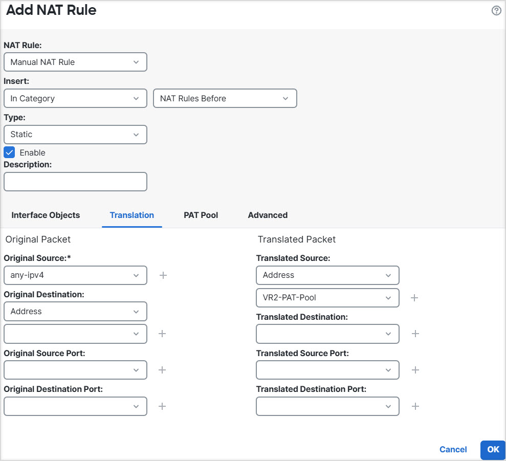
  1. Choose Devices > Device Management > Interfaces.

  2. Click Edit against vr2-inside interface. Specify the IP Address as 192.168.1.1/24. The system now allows you to configure with same IP address of vr1-inside, because the interfaces are separately assigned to two different virtual routers.

  3. Click Ok.

  4. Click Save.

Step 7

Create the NAT rule to PAT inside to outside traffic of VR1 to 10.100.10.1.

  1. Choose Devices > NAT.

  2. Click New Policy > Threat Defense NAT.

  3. Enter InsideOutsideNATRule as the NAT policy name, and select the threat defense device. Click Save.

  4. In InsideOutsideNATRule page, click Add Rule and define the following:

    • NAT Rule—Select Manual NAT Rule.

    • Type—Select Dynamic.

    • Insert—Above, if any dynamic NAT rule exists.

    • Click Enabled.

    • In Interface Objects, select vr1-interface object and click Add to Source (If the object is not available, create one in Object > Object Management > Interface), and select outside as Add to Destination.

    • In Translation, for Original Source, select any-ipv4. For Translated Source, click Add and define host object VR1-PAT-Pool with 10.100.10.1. Select VR1-PAT-Pool as shown in the figure below:

  5. Click Ok.

  6. Click Save.

Step 8

Add NAT rule to PAT inside to outside traffic of VR2 to 10.100.10.2.

  1. Choose Devices > NAT.

  2. Edit InsideOutsideNATRule to define the VR2 NAT rule:

    • NAT Rule—Select Manual NAT Rule.

    • Type—Select Dynamic.

    • Insert—Above, if any dynamic NAT rule exists.

    • Click Enabled.

    • In Interface Objects, select vr2-interface object and click Add to Source (If the object is not available, create one in Object > Object Management > Interface), and select outside as Add to Destination.

    • In Translation, for Original Source, select any-ipv4. For Translated Source, click Add and define host object VR2-PAT-Pool with 10.100.10.2. Select VR2-PAT-Pool as shown in the figure below:

  3. Click Ok.

  4. Click Save.

Step 9

To configure the access control policy that allows traffic from the vr1-inside and vr2-inside interfaces to the outside interface, you need to create security zones. Use Object > Object Management > Interface. Choose Add > Security Zone and create security zones for vr1-inside, vr2-inside, and outside interfaces.

Step 10

Choose Policies > Access Control and configure an access control rule to allow traffic from vr1-inside-zone and vr2- inside-zone to outside-zone.

Assuming that you create zones named after the interfaces, a basic rule that allows all traffic to flow to the Internet will look like the following. You can apply other parameters to this access control policy:
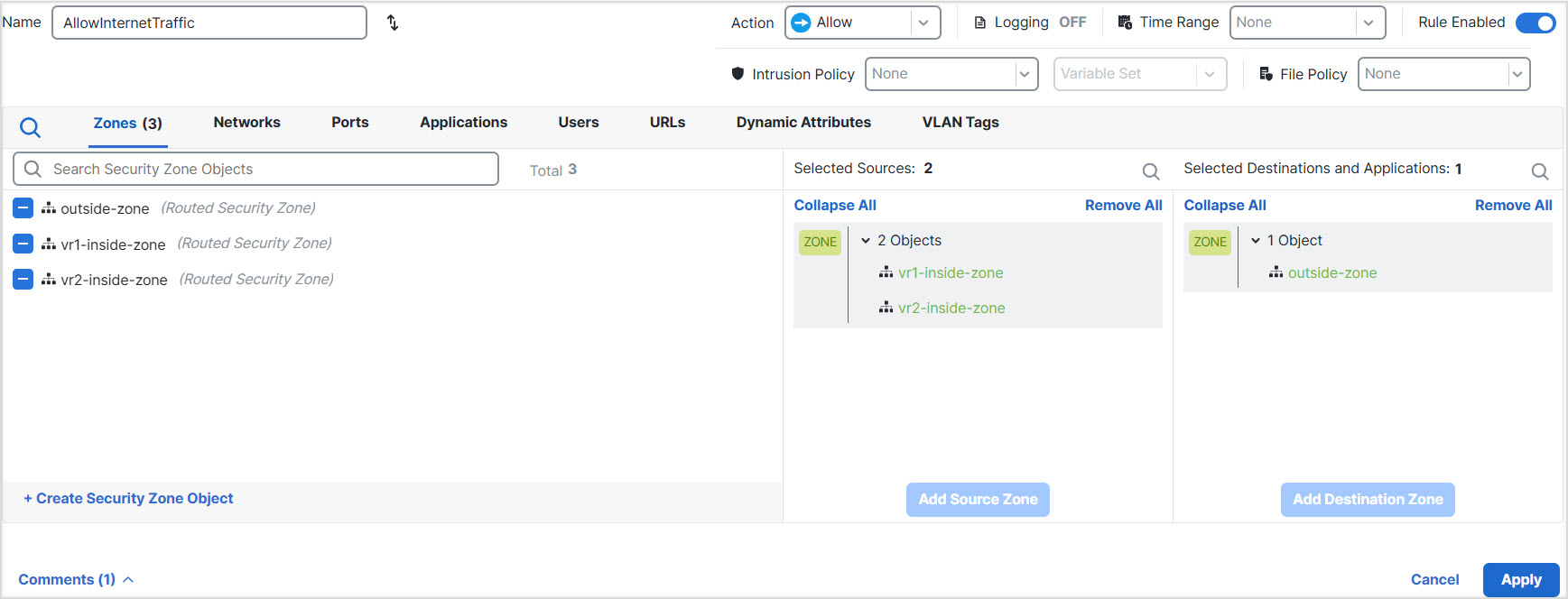