Configure user authentication with overlapping networks
This task enables you to configure user authentication in virtual routing environments where multiple virtual routers share overlapping IP addresses and user networks. The configuration allows users from different domains to access shared resources while maintaining proper access control.
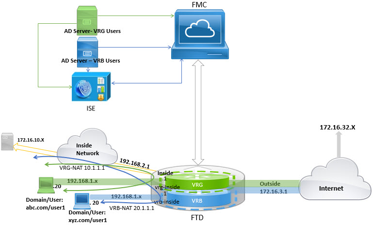
In virtual routing, you can configure multiple virtual routers with overlapping IP and overlapping users. In the example, VRG, and VRB are the virtual routers with overlapping IP - 192.168.1.1/24. The users on two different domains are also on overlapping network IP 192.168.1.20. For VRG and VRB users to access the shared server 172.16.10.X, leak routes to the global virtual router. Use source NAT to handle the overlapping IP. For controlling the access from VRG and VRB users, you must set user authentication in Cloud-Delivered Firewall Management Center. Cloud-Delivered Firewall Management Center uses realms, Active Directories, Identity source, and Identity rules and policies for authenticating user identity. Because Firewall Threat Defense does not have direct role in authenticating users, user access is managed only through the access control policy. For controlling traffic from the overlapping users, use Identity policy and rules to create access control policy.
Before you begin
This example assumes that you have:
-
Two AD servers for the VRG and VRB users.
-
ISE with the two AD servers added.
Follow these steps to configure user authentication with overlapping networks:
Procedure
Step 1 | Configure the inside interface of the device for VRG: |
Step 2 | Configure the inside interface of the device for VRB: |
Step 3 | Configure VRG and the static default route leak to the inside interface of the Global router for the VRG users to access the common server 172.16.10.1:
|
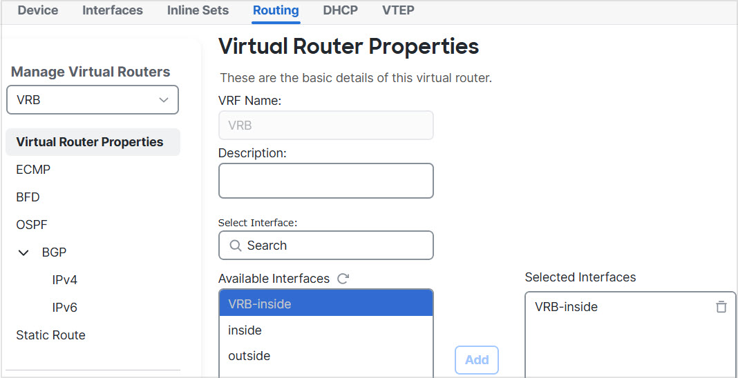
Step 4 | Configure VRB and the static default route leak to the inside interface of the Global router for the VRB users to access the shared server 172.16.10.x:
|
Step 5 | Revisit the VRB-inside interface configuration:
|
Step 6 | Add NAT rules for the source objects VRG and VRB. Click . |
Step 7 | Click . |
Step 8 | Enter a NAT policy name, and select the Firewall Threat Defense device. Click Save. |
Step 9 | In the NAT page, click Add Rule and define the following source NAT for VRG:
|
Step 10 | Click Ok. |
Step 11 | In the NAT page, click Add Rule and define the following source NAT for VRB:
|
Step 12 | Click Save. The NAT rule looks like this: 
|
Step 13 | Add the two unique AD servers in Cloud-Delivered Firewall Management Center one for each VRG and VRB users—choose . |
Step 14 | Click New Realm and complete the fields. For detailed information on the fields, see Realm fields. |
Step 15 | For controlling the access from VRG and VRB users, define 2 Active Directories, see Realm directory and synchronize fieldssee Create an LDAP realm or an Active Directory realm and realm directory |
Step 16 | Add ISE in Cloud-Delivered Firewall Management Center—choose . |
Step 17 | Click Identity Services Engine and complete the fields. For detailed information on the fields, see Configure ISE/ISE-PIC for user control using a realm. |
Step 18 | Create Identity policy, rules, and then define access control policy for controlling access of overlapping users from VRG and VRB. |


You have successfully configured user authentication for virtual routers with overlapping networks. VRG and VRB users can now access the shared server through proper NAT translation and authentication controls, with distinct identity policies managing access for each user group.