Secure traffic from networks with multiple virtual routers over a site-to-site VPN with dynamic VTI
This task enables ISPs to create virtual routers and associate dynamic VTIs with these virtual routers to extend the capabilities of dynamic VTIs in their network. You can associate dynamic VTIs either with global or user-defined virtual routers.
ISPs have different segmented networks for different customers. You can create virtual routers, associate dynamic VTIs with these virtual routers, and extend the capabilities of dynamic VTIs in your network. You can associate dynamic VTIs either with global or user-defined virtual routers. A single threat defense device can act as a dynamic VTI hub with a global or one or more user-defined virtual routers. Each user-defined virtual router can be one customer network.
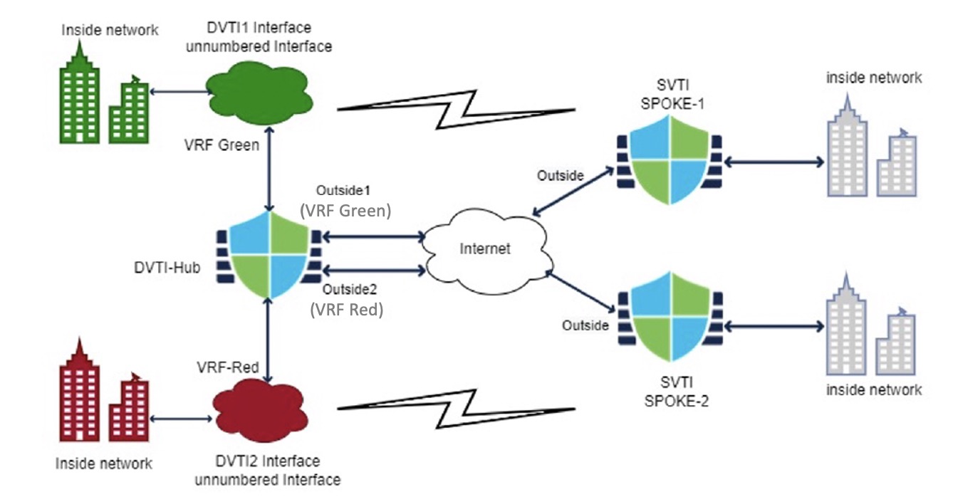
Let us consider an example where route-based site-to-site VPNs are configured between two company headquarter networks and their two branch office networks. The ISP's threat defense, a dynamic VTI hub, manages the two company headquarter networks with two user-defined virtual routers: VRF green and VRF red. The dynamic VTI hub establishes a site-to-site VPN between:
-
Customer 1 (VRF green) and Branch 1 (SVTI spoke 1)
-
Customer 2 (VRF red) and Branch 2 (SVT2 spoke 2)
Procedure
Step 1 | Configure a dynamic VTI interface on the hub.
|
Step 2 | Configure static VTI on spoke 1.
|
Step 3 | Configure a route-based site-to-site VPN between hub and SVTI spoke 1.
|
Step 4 | Configure the two virtual routers. |
Step 5 | Assign all the interfaces to the virtual routers. |
Step 6 | Repeat steps 5a - c for VRF red. |
Step 7 | Configure the routing policy for the virtual router.
|
You have successfully configured networks with multiple virtual routers over a site-to-site VPN with dynamic VTI, enabling ISPs to manage different segmented networks for different customers through virtual routers.
What to do next
Select the hub and spoke devices and click Deploy. After the deployment, you can monitor the VPN tunnels in the Site-to site monitoring dashboard ().
You can also use the commands listed in Monitor virtual routers to view and troubleshoot the virtual router.