Manage overlapping segments in routed firewall mode with BVI interfaces
This task allows you to deploy single Firewall Threat Defense between multiple overlapping networks transparently and/or deploy the firewall between the hosts of same network by configuring BVI per virtual router.
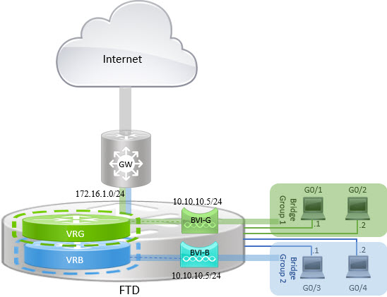
BVI is a virtual interface within a router that acts like a normal routed interface. It does not support bridging, but represents the comparable bridge group to routed interfaces within the router. All the packets coming in or going out of these bridged interfaces, pass through the BVI interface. The interface number of the BVI is the number of the bridge group that the virtual interface represents.
In the following example, BVI-G is configured in VRG and Bridge Group 1 is the routed interface for interfaces G0/1 and G0/2. Similarly, BVI-B is configured in VRB and Bridge Group 2 is the routed interface for interfaces G0/3 and G0/4. Consider that both BVIs have the same IP subnet address, say 10.10.10.5/24. Because of virtual routers, the network is isolated on the shared resources.
Procedure
Step 1 | Choose . Edit the required device. |
Step 2 | In Interfaces, choose .
|
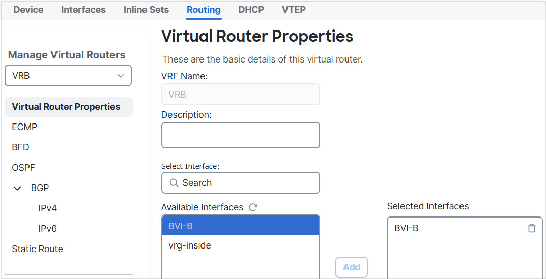
Step 3 | Create virtual router, say VRG, and select BVI-G as its network:
|
Step 4 | Create virtual router, say VRB, and select BVI-B as its network:
|
Step 5 | Revisit the BVI-B configuration:
If you want to enable inter-BVI communication, use an external router as default gateway. In overlapping BVI scenarios, as in this example, use twice NAT external router as gateway to establish inter-BVI traffic. When configuring NAT for the members of a bridge group, you specify the member interface. You cannot configure NAT for the bridge group interface (BVI) itself. When doing NAT between bridge group member interfaces, you must specify the real and mapped addresses. You cannot specify "any" as the interface. |


You have successfully configured BVI interfaces per virtual router to manage overlapping segments in routed firewall mode. The virtual routers isolate the network on shared resources, allowing the use of same IP subnet addresses for both BVIs.