Allow RA VPN access to internal networks in virtual routing
Allow Secure Client users to connect to user-defined virtual router networks by configuring route leaks between the global virtual router and user-defined virtual routers.
On virtual routing-enabled devices, RA VPN is supported only on global virtual router interfaces. This example provides the procedure that allows your Secure Client user to connect to user-defined virtual router networks.
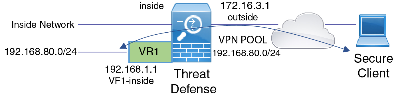
In the following example, the RA VPN (Secure Client) user connects to the outside interface of Firewall Threat Defense at 172.16.3.1, and is given an IP address within the pool of 192.168.80.0/24. The user can access the inside network of only the global virtual router. To allow traffic flow through the network of the user-defined virtual router VR1, namely 192.168.1.0/24, leak the route by configuring the static routes on global and VR1.
Before you begin
This example assumes that you have already configured the RA VPN, defined the virtual routers, and configured and assigned the interfaces to the appropriate virtual routers.
Follow these steps to allow RA VPN access to internal networks in virtual routing:
Procedure
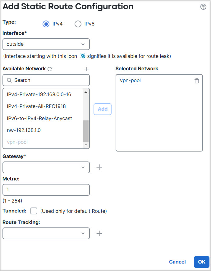
Step 1 | Configure route leak from Global virtual router to the user-defined VR1:
|
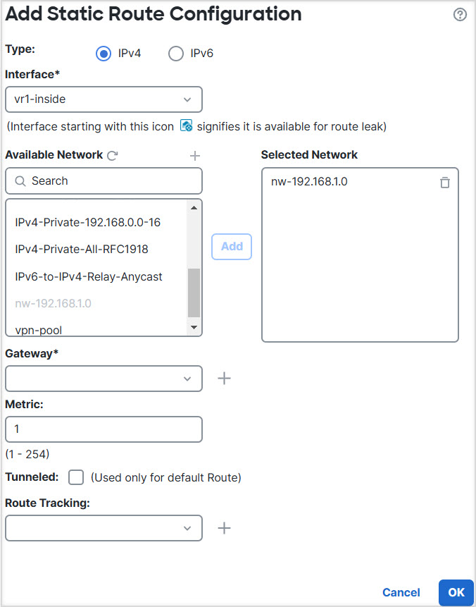
Step 2 | Configure the route leak from VR1 to the Global virtual router:
|
Secure Client users can now access networks in both the global virtual router and the user-defined VR1 virtual router through the configured route leaks.
What to do next
If RA VPN address pool and the IP addresses in the user-defined virtual router overlap, you must also use static NAT rules on the IP addresses to enable proper routing. Alternatively, you can change your RA VPN address pool so that there is no overlap.