Route traffic between two overlapping network hosts in virtual routing
Configure NAT rules to manage overlapping network hosts and enable communication between hosts on different virtual routers that have the same network address.
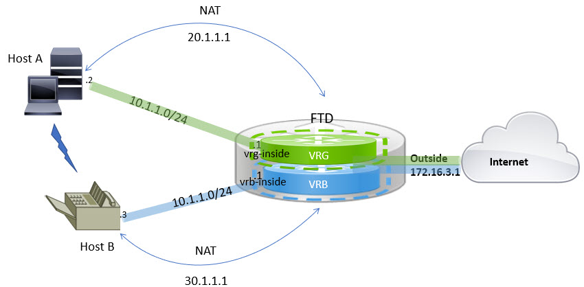
You can configure hosts on the virtual routers that have same network address. If the hosts want to communicate, you can configure twice NAT. This example provides the procedure to configure the NAT rules to manage the overlapping network host.
In the following example, two hosts Host A and Host B belong to different virtual routers: VRG (interface VRG-inside), VRB (interface VRB-inside) respectively with the same subnet 10.1.1.0/24. For both the hosts to communicate, create a NAT policy where, VRG-Host interface object would use a mapped NAT address - 20.1.1.1, and VRB-Host interface object would use a mapped NAT address - 30.1.1.1. Thus, Host A uses 30.1.1.1 to communicate to Host B; Host B uses 20.1.1.1 to reach Host A.
Before you begin
This example assumes that you have already configured:
-
VRG-inside and VRB-inside interfaces are associated with virtual routers: VRG and VRB respectively and VRG-inside and VRB-inside interfaces configured with same subnet address (say, 10.1.1.0/24).
-
Interfaces zones VRG-Inf, VRB-Inf created with VRG-inside and VRB-inside interfaces respectively.
-
Host A in VRG with VRG-inside as default gateway; Host B in VRB with VRB-inside as default gateway.
Follow these steps to route traffic between two overlapping network hosts in virtual routing:
Procedure
Step 1 | Create the NAT rule to handle traffic from Host A to Host B. In the Cloud-Delivered Firewall Management Center, choose . |
Step 2 | Click . |
Step 3 | Enter a NAT policy name, and select the Firewall Threat Defense device. Click Save. |
Step 4 | In the NAT page, click Add Rule and define the following:
When you run the show NAT detail command on the Firewall Threat Defense device, you will see an output similar to this: |
Step 5 | Click Ok. |
Step 6 | Click Save. The NAT rule looks like this: When you deploy the configuration, a warning message appears: 
|
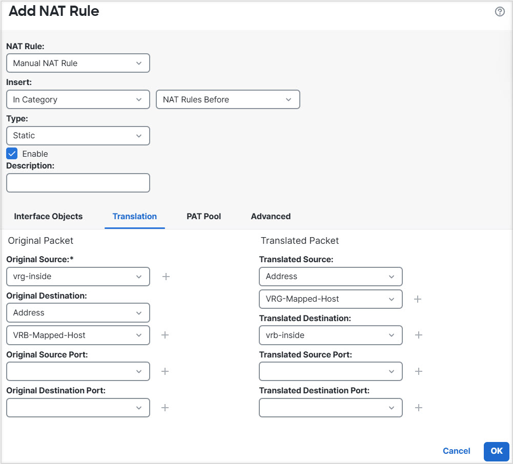
The NAT rule is configured to enable communication between Host A and Host B on overlapping network addresses. Host A uses 30.1.1.1 to communicate with Host B, and Host B uses 20.1.1.1 to reach Host A.