Route to a distant server through virtual routers
This task enables network separation while maintaining connectivity to servers across different virtual routing domains. You can create multiple virtual routers to maintain separate routing tables for groups of interfaces and interconnect them to reach hosts that are multiple hops away.
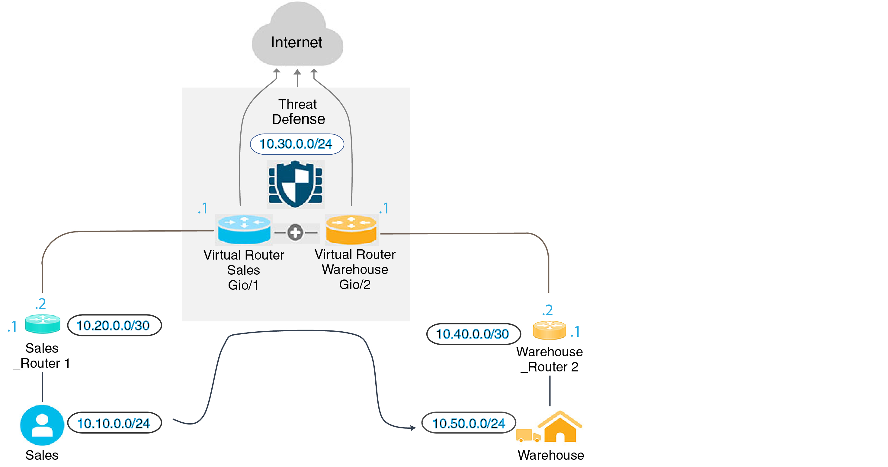
In virtual routing, you can create multiple virtual routers to maintain separate routing tables for groups of interfaces, thereby achieve network separation. In some scenarios, you may need to access a server that is reachable only through a separate virtual router. This example provides the procedure that interconnects virtual routers to reach to a host that is multiple hops away.
Consider an example, where a member of the sales department of a garment company wants to look up at the stock maintained by the warehousing department of its factory unit. In a virtual routing environment, you need to leak route between virtual routers where destination (warehousing department) is multiple hops away from sales department. This route leaking is done by adding multihop route leak, where, you configure a static route in Sales virtual router(source) to an interface in Warehouse virtual router (destination). As the destination network is multi-hop away, you also need to configure the Warehouse virtual router with the route to the destination network, namely 10.50.0.0/24.
Before you begin
This example assumes that you have already configured Sales_Router1 to route traffic from 10.20.0.1/30 interface to 10.50.0.5/24.
Follow these steps to route to a distant server through virtual routers:
Procedure
Step 1 | Configure the inside interface (Gi0/1) of the device to be assigned to Sales virtual router. |
Step 2 | Configure the inside interface (Gi0/2) of the device to be assigned to Warehouse virtual router. |
Step 3 | Create Sales and Warehouse virtual routers and assign their interfaces.
|
Step 4 | Revisit the VR-Warehouse interface configuration.
|
Step 5 | Create network objects for the warehouse server—10.50.0.0/24, and for the warehouse gateway— 10.40.0.2/30. |
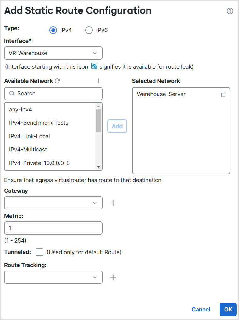
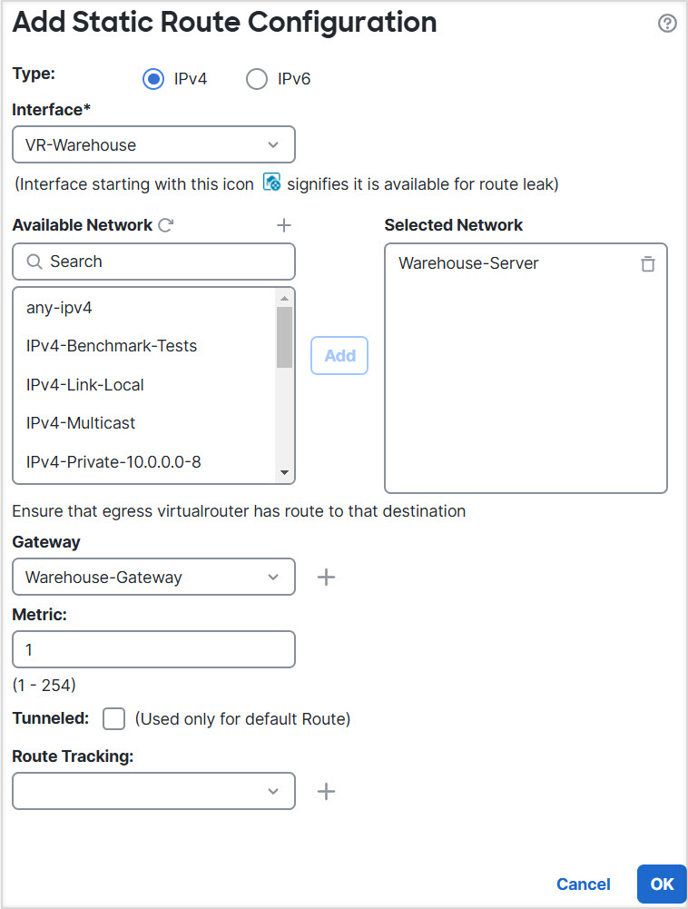
Step 6 | Define the route leak in Sales that points to the VR-Warehouse interface.
|
Step 7 | In the Warehouse virtual router, define the route that points to the Warehouse Router 2 gateway.
|
Step 8 | Configure access control rule that allows access to the warehouse server. For creating the access control rule, you need to create security zones. Use . Choose and create security zones for VR-Sales and VR-Warehouse; for Warehouse-Server network object, create a Warehouse-Server interface group (Choose ). |
Step 9 | Choose and configure an access control rule to allow traffic from the source interfaces in the Sales virtual router to the destination interfaces in the Warehouse virtual router for the destination Warehouse-Server network object. For example, if the interfaces in Sales are in the Sales-Zone security zone, and those in Warehouse are in the Warehouse-Zone security zone, the access control rule would look similar to this:  |
The route leak configuration enables traffic from the Sales virtual router to reach the warehouse server through the Warehouse virtual router. The access control rule allows the required traffic between the security zones.