Secure traffic from networks in multiple virtual routers over a site-to-site VPN
This task allows you to secure connections from or to networks hosted within user-defined virtual routers over the site-to-site VPN by configuring route leaking between virtual routers and updating the VPN connection profile.
On virtual routing-enabled devices, Site-to-Site VPN is supported only on global virtual router interfaces. You cannot configure it on an interface that belongs to a user-defined virtual router. This procedure allows you to secure the connections from or to networks hosted within user-defined virtual routers over the site-to-site VPN. You also need to update the site-to-site VPN connection to include the user-defined virtual routing networks.
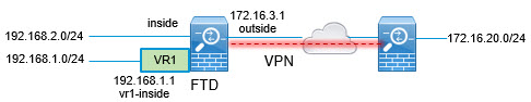
Let us consider a scenario, where, a site-to-site VPN is configured between a branch office network to a company headquaters network; the Firewall Threat Defense in the branch office having virtual routers. In this case, the site-to-site VPN is defined on the outside interface of the branch office at 172.16.3.1. This VPN includes the inside network 192.168.2.0/24 without extra configuration, because the inside interface is also part of the global virtual router. But, to provide site-to-site VPN services to the 192.168.1.0/24 network, which is part of the VR1 virtual router, you must leak the route by configuring the static routes on global and VR1, and add the VR1 network to the site-to-site VPN configuration.
Before you begin
This example assumes that you have already configured the site-to-site VPN between the 192.168.2.0/24 local network and the 172.16.20.0/24 external network, defined the virtual routers, and configured and assigned the interfaces to the appropriate virtual routers.
Follow these steps to secure traffic from networks in multiple virtual routers over a site-to-site VPN:
Procedure
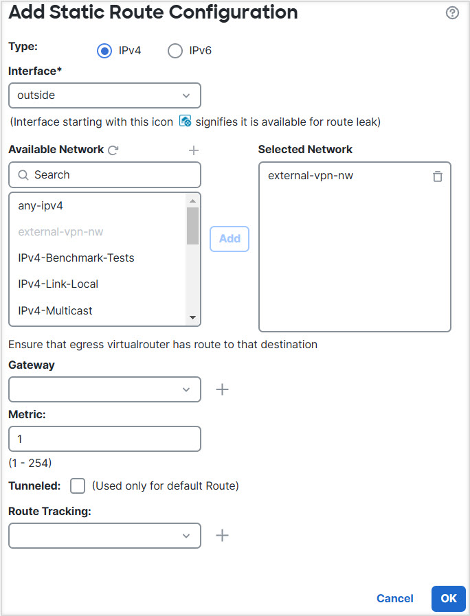
Step 1 | Configure route leak from the Global virtual router to the user-defined VR1:
|
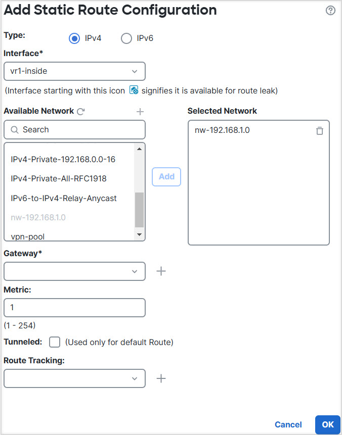
Step 2 | Configure the route leak from VR1 to the Global virtual router:
|
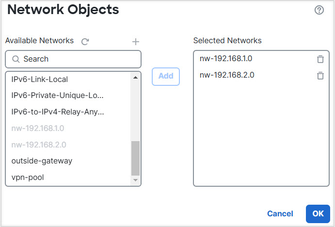
Step 3 | Add the 192.168.1.0/24 network to the site-to-site VPN connection profile:
|
The route leaking configuration allows traffic from networks in user-defined virtual routers to traverse the site-to-site VPN tunnel securely, enabling connectivity between the VR1 network and remote networks protected by the VPN.